Transcription of Experiment # 7 Multiplexers And Demultiplexers
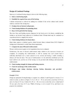
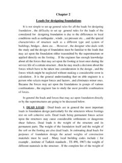
1 Experiment # 7 Multiplexers And Demultiplexers Eng. Waleed Y. Mousa 1 1. Objectives: 1. Understanding how to implement functions using Multiplexers . 2. To study demultiplexer. 2. Theory: Multiplexers : In electronics, a multiplexer (or mux) is a device that selects one of several analog or digital input signals and forwards the selected input into a single line. A multiplexer of 2n inputs has n select lines, which are used to select which input line to send to the output. A 2n-to-1 multiplexer sends one of 2n input lines to a single output line. A multiplexer has two sets of inputs: 2n data input lines n select lines, to pick one of the 2n data inputs The mux output is a single bit, which is one of the 2n data inputs. 2-to-1 Mux The simplest multiplexer is a 2-to-1 mux Q = S D0 + S D1 The select bit S controls which of the data bits D0-D1 is chosen: If S=0, then D0 is the output (Q=D0).
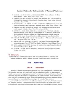
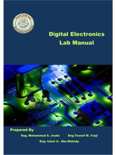
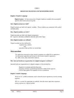
2 If S=1, then D1 is the output (Q=D1). Here is a full truth table for this 2-to-1 mux, based on the equation: Q = S D0 + S D1 2 Here is another kind of abbreviated truth table. 4-to-1 Mux Here is a block diagram and abbreviated truth table for a 4-to-1 mux. Be careful! In Logic Works the multiplexer has an active-low EN input signal. When EN = 1, the mux always outputs 1. Q = S1 S0 D0 + S1 S0 D1 + S1 S0 D2 + S1 S0 D3 Implementing functions with Multiplexers : Muxes can be used to implement arbitrary functions. For a function of n variables follow these steps: 1. Select the type of Mux [2n-1-to-1]. 2. Select (n-1) as selection line. 3. The other input connects as input. 3 Example : Implement following function with multiplexer : Solution: 1.
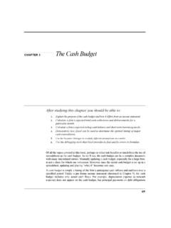
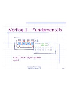
3 The type of Mux [23-to-1] == 8-to-1 mux 2. Select (3) as selection line. == For example (B, C, and D) 3. The other input connects as input. == (A) In terms of B 0 1 2 3 8 9 10 11 4 5 6 7 12 13 14 15 I0 I1 I2 I3 I4 I5 I6 I7 B' B 1 B' 0 B' B' B' 0 B 4 Demultiplexers : The Demultiplexer is combinational logic circuit that performs the reverse operation of multiplexer . It has only one input, n selectors and 2n outputs. Depending on the combination of the select lines, one of the outputs will be selected to take the state of the input. The following figure shows the block diagram and the truth table for 1x4 Demultiplexer. By applying logic '1' to the input, the circuit will do the same function of the typical 2-to-4 Decoder. 5 3. Lab Work: Part 1: 2-to-1 Mux 1) Construct 2-to-1 Mux using KL-33006 block e.
4 (D1=A, D0=B, S=C). Connect inputs A, B to SW0 and SW1. Connect input C to SW3. Part 2: 8-to-1 Mux a) Using Mux KL-33006 block f connect inputs DO D7 to DIP Switch ; inputs C, B, A to DATA Switches SW2, SW1, SW0 respectively, strobe to 0, Y and W to L0, L1 respectively then complete this table. C B A F3 0 0 0 0 0 1 0 1 0 0 1 1 1 0 0 1 0 1 1 1 0 1 1 1 D7 D6 D5 D4 D3 D2 D1 D0 C B A Y 0 0 0 0 0 0 1 1 0 0 0 0 0 0 0 0 0 1 0 0 0 1 0 0 0 1 0 1 0 1 0 1 0 0 0 0 0 1 0 0 0 0 1 1 1 0 0 1 0 0 0 0 1 0 0 0 0 1 0 0 0 0 0 1 0 1 0 1 1 0 0 0 0 0 1 1 0 0 0 0 0 0 0 0 0 1 1 1 6 b) Construct the function, F (A, B, C, D) = (0, 1, 3, 4, 8, 9, 15) from example in terms of A (A is input) using Mux KL-33006 block f. 4. Exercises: 1) Implement F (A, B, C, D) = (3, 8, 12) using Mux: a) In terms of C.
5 B) In terms of D. 2) Implement 8-to-1 mux using tow 4-to-1 mux and one 2-to-1 mux. 3) Implement 1-to-4 dmux using 1-to-2 dmux.