Transcription of Failures Related to Heat Treating Operations - G.E. …
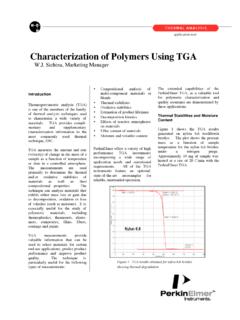
1 Failures Related toHeat Treating Totten, Totten & Associates, LLCM. Narazaki, Utsunomiya University (Japan) Blackwood and Jarvis, Tenaxol , C10212 4 8 Minutes15 30 60124681624103104105 HoursMartensitePearlite startPearlite endBainite endBainite startA1A3 Pearlite startPearlite endBainite endBainite startA1A3 Fig. 1 Time-temperature-transformation diagram of an unalloyed steel containing C. Austenitization tempera-ture, 880 C (1620 F). The temperature A1is where transformation to austenite begins, and temperature A3iswhere the transformation to austenite is complete. Courtesy of Verlag Stahlessen mbH DusseldorfHEAT Treating of all the various steelprocessing methods has the greatest overallimpact on control of microstructure, properties,residual stresses, and dimensional control. Thisarticle provides an overview of the effects ofvarious material and process- Related parameterson residual stress, distortion control, cracking,and microstructure/property relationships as theyrelate to various types of failure .
2 The subjectsthat are discussed include: Phase transformations during heat Treating Metallurgical sources of stress and distortionduring heating and cooling Effect of materials and quench-process designon distortion and cracking Quenchant selection Effect of cooling characteristics on residualstress and distortion Methods of minimizing distortion Tempering Effect of the heat treatment process on micro-structure/property- Related Failures , such ascrackingPhase Transformationduring Heating and CoolingSteel TransformationProperties such as hardness, strength, ductil-ity, and toughness are dependent on the micro-structural products that are present in steel. Thefirst step in the transformation process is to heatthe steel to its austenitizing temperature. Thesteel is then cooled rapidly to avoid the forma-tion of pearlite, which is a relatively soft trans-formation product; to maximize the formation ofmartensite, a relatively hard transformationproduct; and to achieve the desired most common transformational productsthat may be formed from austenite in quench-hardenable steels are, in order of formation withdecreasing cooling rate: martensite, bainite,pearlite, ferrite, and cementite.
3 The formation ofthese products and the proportions of each aredependent on the time and temperature coolinghistory of the particular alloy and the elementalcomposition of that alloy. The transformationproducts formed are typically illustrated with theuse of transformation diagrams, which show thetemperature-time dependence of the microstruc-ture formation process for the alloy beingstudied. Two of the most commonly used trans-formation diagrams are time-temperature-trans-formation (TTT) and continuous cooling trans-formation (CCT) ,also called isothermal transformation di-agrams, are developed by heating small samplesof steel to the temperature where austenite trans-formation structure is completely formed, that is,the austenitizing temperature (TA), and then rap-idly cooling to a temperature intermediate be-tween the austenitizing and the martensite start(Ms) temperature and then holding for a fixedperiod of time until the transformation is com-plete, at which point the transformation productsare determined.
4 This is done repeatedly until aTTT diagram is constructed, such as that shownfor an unalloyed steel (American Iron and SteelInstitute, or AISI, 1045) in Fig. 1. Time-tem-perature-transformation diagrams can only beread along the isotherms. The temperature A1iswhere transformation to austenite begins, , C1012 4 8 Minutes15 30 6012468162410260103105104 HoursMartensitePearlite startPearlite endA1A3 Pearlite startPearlite endA1A3 Bainite endBainite endBainite startBainite startFig. 2 Continuous cooling transformation diagram of an unalloyed steel containing C. Austenitization tem-perature, 880 C (1620 F). Courtesy of Verlag Stahlessen mbH Dusseldorf(a)(b)(c)Fig. 3 Crystal structures. (a) Austenite (fcc). (b) Ferrite(bcc). (c) Martensite (bct)temperature A3is where the transformation toaustenite is Cooling Transformation , samples of a given steelmay be continuously cooled at different specifiedrates, and the proportion of transformation prod-ucts formed after cooling to various temperaturesintermediate between the austenitizing tempera-ture and the Msmay be determined in order toconstruct a CCT diagram, such as the one shownfor an unalloyed carbon steel (AISI 1045) in Continuous cooling transformation curvesprovide data on the temperatures for each phasetransformation, the amount of transformationproduct obtained for a given cooling rate withtime, and the cooling rate necessary to obtainmartensite.
5 The critical cooling rate is dictatedby the time required to avoid formation of pearl-ite for the particular steel being quenched. As ageneral rule, a quenchant must produce a coolingrate equivalent to, or faster than, that indicatedby the nose of the pearlite transformationcurve in order to maximize martensite transfor-mation product. Continuous cooling transfor-mation diagrams can only be read along thecurves of different cooling :Although it is becoming increas-ingly common to see cooling curves (tempera-ture-time profiles) for different quenchants, suchas oil, water, air, and others, superimposed oneither TTT or CCT diagrams, this is not a rig-orously correct practice, and various errors areintroduced into such analysis due to the inher-ently different kinetics of cooling used to obtainthe TTT or CCT diagrams (described previously)versus the quenchants being represented.
6 If acooling curve is to be superimposed on a trans-formation diagram, a CCT, not a TTT, diagramshould be Crystal StructureWhen steel is slowly cooled, it undergoes acrystal structure (size) change as it transformsfrom a less densely packed austenite (face-cen-tered cubic, or fcc) to a more densely packedbody-centered cubic (bcc) structure of ferrite. Atfaster cooling rates, the formation of ferrite issuppressed, and martensite, which is an even lessdensely packed body-centered tetragonal (bct)structure than austenite, is formed. Illustrationsof these crystal structures are provided in Fig. results in a volumetric expansion at the Mstemperature, as shown in Fig. 5 shows that the crystal lattice of aus-tenite expands with increasing carbon content(Ref 1). It has been reported that, typically, whena carbide-ferrite mixture is converted to marten-site, the resulting expansion due to increasingcarbon content is approximately C and at C (Ref 1).
7 Thefractional increase in size when austenite is con-verted to martensite is approximately for eutectoid compositions. This illustratesthe effect of carbon structure and steel transfor-mation on residual stresses and distortion lead-ing to dimensional of VolumetricChange due to Steel TransformationIn the previous discussion, it has been shownthat there are various microstructures possible onheating and cooling of steel, and that the poten-tial microstructural transformations that are pos-sible for a given steel are illustrated by their CCTor TTT diagrams. Furthermore, dimensionalchanges are possible, depending on the carboncontent and microstructural transformation prod-uct formed. Table 1 summarizes the atomic vol-umes of different microstructural components asa function of carbon content (Ref 2).
8 Table 2provides an estimate of volumetric changes as afunction of carbon content for different metal-lurgical transformations (Ref 3, 4).Volumetric expansion occurring as a result ofquenching can be estimated from (Ref 5):DV/V 100 (100 Vc Va) Va( )(Eq 1)where (DV/V) 100 equals the percentagechange in volume,Vcequals the percentage byvolume of undissolved cementite, (100 Vc Va) equals the percentage by volume of marten-site,Vaequals the percentage by volume of aus-tenite, and C equals the percentage by weight ofcarbon dissolved in austenite and the value of (DV/V) is known or can be com-puted, then internal stresses that are developedin a part due to temperature differences (DT)arising from either one-dimensional heating orcooling can be estimated from (Ref 6): Failures Related to heat Treating Operations / , wt%Martensite, AAustenite, Ac/ Fig.
9 5 Carbon content versus lattice parameters of (re-tained) austenite and martensite at room the top of the graph is the lattice parameterof fcc the lower half of the graph arethe lattice parameters for tetragonal martensite. The ratioofc/afor martensite as a function of carbon content is 1600120010008006004002000200300400500600 700800 expansion, %Temperature, CTemperature, FAusteniteHigh-temperaturetransformation Very slowcoolingPearliteRapidquenchingMartens iteformsAusteniteAusteniteAusteniteHigh- temperaturetransformationVery slowcoolingPearliteRapidquenchingMartens iteformsFig. 4 Steel expansion and contraction on heating andcoolingTable 1 Atomic volumes of selectedmicrostructural constituents of ferrousalloysPhaseApparent atomic volume, A C(a) C(a) C(a)(a) C % carbonr E e E 1 3(DV/V) E DT(Eq 2)whereris stress,eis strain,E(modulus of elas-ticity) 2 105N/mm2, and (coefficient ofthermal expansion) 10 5.
10 Relative vol-ume changes due to phase transformation are il-lustrated in Fig. 6 (Ref 6).Figure 7 shows that stresses, such as an in-crease in hydrostatic pressure, accelerate phasetransformations (Ref 7). This occurs whether thestresses are tensile or compressive and results inaccelerated austenite decomposition and in-creased Mstemperature. The strain of this pro-cess is often estimated as being equal to the vol-umetric expansion divided by 3 (Ref 8).Transformation plasticity is a process whereby astress affects linear strain. This is illustrated inFig. 8, where the effect of applied stress on mar-tensitic transformation strain is shown (Ref 8).Generally, the Mstemperature is increased bytensile stress and decreased by hydrostatic pres-sure. Figure 9 shows that stress exhibits verylarge effects on the start and stop times for pear-litic transformation (Ref 7).