Transcription of Fastening Tips for HardiePlank Lap Siding TECHNICAL ...
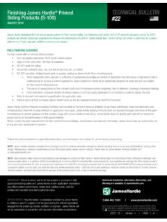
1 USTB 17 | Version 3 | PAGE 1 of 2 For complete installation information BULLETINF astening Tips for HardiePlank Lap SidingSEPTEMBER 2014#17 Scope: This TECHNICAL Bulletin addresses approved Fastening techniques when using HardiePlank Lap lap Siding may be used with fasteners approved by ICC-ES ESR-2290 spaced in accordance with the Wind Load Tables. Fasteners must be corrosion resistant, galvanized or stainless NAILING (PREFERRED INSTALLATION)James Hardie prefers and recommends installation of HardiePlank lap Siding by the blind nailing technique, such that fasteners are hidden by the course above. Fasteners shall be installed between 1 in. and 3/4 in. from the top edge and no closer than 3/8 in. from the ends of the plank. PIN BACKSP inning the plank down at the bottom edge is a common practice called pin back.
2 It is used to correct high nailing , loose planks, gaps or rattling. Pinning of the butt joints is not intended to increase wind load values; and shall be installed 3/8 in. from end and between 3/4 in. and 1 in. from bottom edge. The fi nish nail shall be nailed fl ush to the surface (not countersunk), must be corrosion resistant ( galvanized or stainless) and does not provide structural support. For best aesthetics nail heads should be touched-up to color are hidden by the course aboveBlind NailingNails are driven through the sheathing into the Nailing MeasurementsKeep nails3/8 in. fromends of for blind nailing should be between 1 in. and 3/4 in. from the top of the nailBlind nail3/4 1/4 in. : Failure to install and fi nish this product in accordance with applicable building codes and James Hardie written application instructions may affect system performance, violate local building codes, void the product-only warranty and lead to personal ADVICE: Any information or assistance provided by James Hardie in relation to specifi c projects must be approved by the relevant specialists engaged for the project eg.
3 Builder, architect or engineer. James Hardie will not be responsible in connection with any such information or | Installation Information, Warranties, and Warning are available at 2014 James Hardie Building Products, Inc. All rights reserved. TM, SM, and denote trademarks or registered trademarks of James Hardie Technology Limited. The is a registered trademark of James Hardie Technology Limited. TB1017 09/14 USTB 17 | Version 3 | PAGE 2 of 2#17 NOTE: These installation details are intended to be used as a guide only. Refer to the manufacturer s instructions and consult with an architect or licensed design professional. Exposed fasteners are driven through the face of the NailingDrive fasteners only where planks Nailing MeasurementsKeep nails3/8 in.
4 Fromendsof for face nailing should be between 3/4 in. and 1 in. from the bottom of the Selection For Face NailingSteel FramingscrewsscrewsRibbed Bugle-Head No. in. x Bugle-Head No. in. x in. x in.[AKN-100] .100 in. x .25 in. x in. x .267 in. x 2 in. x .221 in. x nailsiding in. x .221 in. x 2 NAILINGFace nailing is applicable where dictated by building code, in high wind areas, and when Fastening is to OSB or equivalent sheathing without penetrating into studs. Face nailing exposes the fastener head to the elements and allows for the fastener to penetrate through two sheets of overlapped plank. Fasteners shall be installed between 3/4 in. and 1 in. from the bottom edge of the board and the head must be snug, not counter sunk or overdriven.
5 The use of roofi ng nails (11GA) are not approved in this application. Where ColorPlus products are used, the fastener head must be touched-up for color NAILINGD ouble nailing refers to the combined use of blind nailing and face nailing. Double nailing may be applicable in circumstances of repair or when a correction is necessary to meet Fastening requirements that would otherwise require replacement of the Siding . Additional care must be taken to assure that Fastening of the face nail does not contact the blind nail and that spacing does not induce damage to the lapped double nailed assemblies, the wind load value for face nailing is not additive to the wind load value for blind nailing. To determine the wind load value for a double nailed assembly locate the blind nailing and the face nailing wind values as listed in the product s evaluation report (ICC-ES ESR-2290), the greater of the two wind load values shall be used.
6