Transcription of Features & Benefits Product Highlights - Vicor …
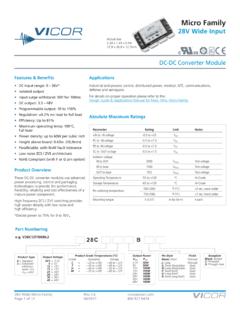
1 DC-DC Converters50 to 200 WattsVI-200VE-200VI-200 DC-DC Converters Rev 1 of 7 08/2017 SNRTLCUSCUS Features & Benefits Isolated output Up to 50W/in3 cURus, cT Vus Up to 90% efficiency Size: x x (116,8 x 61,0 x 12,7mm) Remote sense and current limit OVP, thermal shutdown Logic disable Wide range output adjust Compatible power booster modules ZCS power architecture Low noise FM control CE Marked RoHS compliant (VE-200) Product HighlightsThe VI-200 family, with over 14 million units shipped, is Vicor s broad series of zero-current-switching component-level DC-DC at frequencies up to 2 MHz, VI-200 family converters offer exceptional power density, efficiency, noise performance, reliability and ease of use. Booster modules (VI-Bxx) provide a simple, cost-effective, off-the-shelf solution for higher power output requirements.
2 One or more boosters may be used to create synchronous arrays capable of supplying several kilowatts of output flexibility of Vicor s power components is also available in half-size, half-power VI-J00 NumberingNote: For additional packaging options, please see page 5. VI 2 6 1 C W Family Series Input Output Grade Power VI = Non-RoHS 2 = 200 0 = 12V N = 48V Z = 2V M = 10V K = 40V E = 10 to 85 C 5V < 5V VE = RoHS B = Booster V = 24V 4 = 72V Y = 1 = 12V 4 = 48V C = 25 to 85 C U = 200W U = 40A 1 = 24V T = 110V 0 = 5V P = H = 52V I = 40 to 85 C V = 150W V = 30A W = 24V 5 = 150V X = 2 = 15V F = 72V M = 55 to 85 C W = 100W W = 20A 2 = 36V 6 = 300 V W = N = D = 85V X = 75W X = 15A 3 =
3 48V 7 = 150/300V V = 3 = 24V B = 95V Y = 50W Y = 10A T = L = 28V R = J = 36 VVI-200 DC-DC Converters Rev 2 of 7 08/2017VI-200, VE-200 Converter Specifications(Typical at TBP = 25 C, nominal line and 75% load, unless otherwise specified.)Input SpecificationsMaximum Power Available for VI-2xx-xx [a]InputOutputVoltageNom. (Range)Low Line75%Max PowerTransient [b]VIN DesignatorsVOUT (10 20)n/a220 XXXXXXXXXXXXXXXXXXXXXX24 (10 36)n/an/aV--XYYYYYXXXXXXXXXXX--------24 (21 32)18361 UUUUUUVVUUUUUUUUUUUUUU24 (18 36)n/an/aWVVVVVVWWVVVVVVVVVVVVVV36 (21 56)18602 WVWWWWWWWWWWWWWWWWW------48 (42 60)36723 UUUUUUUUUUUUUUUUUUUUUU48 (36 76)n/an/aNUUUUUUUUUUUUUUUUUUUUUU72 (55 100)451104vUUUUUVVUUUUUUUUUUUUUU110 (66 160)n/an/aTVVVVVVWWVVVVVVVVVVVV----150 (100 200)85 [c]2155 UUVVVVVVUUUUUUUUUUUUUU150 (100 375)n/an/a7 WWYYYYWWWWWWWWWWWWW------300 (200 400)170 [d]4256 UUUUUUVVUUUUUUUUUUUUUU[a] For additional output power, booster modules are available.
4 (VI-Bxx-xx).[b] Transient voltage for 1 second.[c] 12 VOUT, , 15 VOUT, 200W models are limited to 90 VDC.[d] 15 VOUT, 200W models are limited to E-GradeVI-200 C-, I-, M-GradeParameterMinTypMaxMinTypMaxUnitsT est ConditionsInrush charge120 x 10-6120 x 10-6200 x 10-6 CoulombsNominal lineInput reflectedripple current pp10%10%IINN ominal line, full loadInput ripple rejection25+20 Log30+20 LogdB120Hz, nominal line20+20 LogdB2400Hz, nominal lineNo load power ()VINVOUT()VINVOUT()VI-200 DC-DC Converters Rev 3 of 7 08/2017VI-200, VE-200 Converter Specifications (Cont.)(Typical at TBP = 25 C, nominal line and 75% load, unless otherwise specified.)[a] 10V to 15V outputs, or V input range have standard trim range 10%. Consult factory for wider trim range. output trim range to , 95V output 50 + 0% trim range.
5 [b] 131% nominal for booster modules.[c] Output voltages of or 5V incorporate foldback current limiting; For output voltages from to consult factory; All other outputs provide constant current CharacteristicsControl Pin SpecificationsVI-200 E-GradeVI-200 C-, I-, M-GradeParameterMinTypMaxMinTypMaxUnitsT est ConditionsSetpoint accuracy1%2% to HL, 10% to Full LoadLoad/line regulation1% to HL, No Load to 10%Output temperature / COver rated term hoursOutput ripple pp:15060100mV20 MHz bandwidth2V, bandwidth10 95V3% bandwidthTrim range [a]50%110%50%110%VNOMT otal remote sense max. neg. legOVP set point125% [b]115%125% [b]135%VNOMR ecycle powerCurrent limit105%135%105%125%IFULL LOADA utomatic restartShort circuit current [c]20%140%20%130%IFULL LOADA utomatic restartVI-200 E-GradeVI-200 C-, I-, M-GradeParameterMinTypMaxMinTypMaxUnitsT est ConditionsGate out impedance5050 OhmsGate in impedance10001000 OhmsGate in open circuit voltage66 VoltsUse open collectorGate in low in low current66mAPower sharing : The permissible load current must never be exceeded during normal, abnormal or test conditions.
6 For additional output related application information, please refer to output connections on page DC-DC Converters Rev 4 of 7 08/2017VI-200, VE-200 Dielectric Withstand CharacteristicsThermal CharacteristicsMechanical SpecificationsProduct Grade TemperaturesMaximum Capacitance, Rated Output Voltage <5 VMaximum Capacitance, Rated Output Voltage 5V[d] No overtemp protection in booster E-GradeVI-200 C-, I-, M-GradeParameterMinTypMaxMinTypMaxUnitsTest ConditionsInput to output3,0003,000 VRMSB aseplate earthedOutput to baseplate500500 VRMSI nput to baseplate1,5001,500 VRMSVI-200 E-GradeVI-200 C-, I-, M-GradeParameterMinTypMaxMinTypMaxUnitsTest ConditionsEfficiency78 88%80 90%Baseplate to sinkthermal C/WattWith Vicor P/N 20266 Thermal shutdown [d](Drivers only)90951059095105 CCool and recycle power to restartVI-200 E-GradeVI-200 C-, I-, M-GradeParameterMinTypMaxMinTypMaxUnitsTest ( ) (178) ( ) ( ) (208) ( )Ounces(Grams)ParameterStorageOperatingUnitsNotesE-20 to +100-10 to + 85 COvertemperature shutdown95 C typical (recycle powerto restart)C-40 to +100-25 to + 85 CI-55 to +100-40 to + 85 CM-65 to +100-55 to + 85 CRated VOUT (V)IOUT Rating (A)CMAX ( F)IOUT Rating (A)CMAX ( F)2 to <3 101500>10 to 4050003 to <5 101000>10 to 405000 Rated VOUT (V)POUT Rating (W)CMAX ( F)POUT Rating (W)CMAX ( F)5 to < 501000>50 to to <10 50400>50 to 20070010 to <28 50400>50 to 200500>28 50150>50 to 200250 Converter Specifications (Cont.)
7 (Typical at TBP = 25 C, nominal line and 75% load, unless otherwise specified.)VI-200 DC-DC Converters Rev 5 of 7 08/2017VI-200, VE-200 Output Connections and ConsiderationsThe permissible load current [e] must never be exceeded during normal, abnormal or test conditions. Converters subject to dynamic loading exceeding 25% of rated current must be reviewed by Vicor Applications Engineering to ensure that the converter will operate dynamic load, light load, or no load conditions, the converter may emit audible noise. Converters that utilize remote sense may require compensation circuitry to offset the phase lag caused by the external output leads and load impedance. Remote Sense leads must be protected for conditions such as lead reversal, noise pickup, open circuit, or excessive output lead resistance between the sense point and the converters output terminals.
8 For applications that may draw more than the rated current, a fast acting electronic circuit breaker must be utilized to protect the converter. Under no circumstance should the rated current be exceeded. Utilizing or testing of current limit or short circuit current will damage the converter. Ensure that the total output capacitance connected to the converter does not exceed the limits on Page products, when not installed in customer units, should be stored in ESD safe packaging in accordance with ANSI/ESD , Protection of Electrical and Electronic Parts, Assemblies and Equipment and should be maintained in a temperature controlled factory/warehouse environment not exposed to outside elements controlled between the temperature ranges of 15 C and 38 C.
9 Humidity shall not be condensing, no minimum humidity when stored in an ESD compliant package.[e] Permissible load current:+OUT+IN IN OUTZero CurrentSwitchingConverterC1aC1bC2aC2bC3F 1 Figure 1 Basic module operation requires fusing, grounding, bypassing capacitors.* See Design Guide & Applications Module OperationNominal Power RatingNominal VOUTC3 ( F) = 400 VIN MinimumVI-200 DC-DC Converters Rev 6 of 7 08/2017VI-200, VE-200+.030 (0,76) (0) Product IDthis surfaceFULL R567894321 Pin # 1 2 3 4 5 6* 7* 8* 9 Function +InGate InGate Out -In +Out+Sense Trim-Sense -Out* Do not connect on booster modulesAluminum (1,0) Dia (7) placesSolder plate over copper (2,0) Dia (2) placesSolder plate over copper alloy .30 .015 (7,6) (0,38) (45,7)(106,7) (12,7) (5,6) MIN (3,0) (116,8)(61,0) (44,5)(7,6) (3,8) (53,3).
10 40 (10,2) .35 .015 (8,9) (0,38) (35,6) (25,4).70(17,8)(91,4)VI-200 Mechanical (12,7) .15(3,8) . (2,0) Dia (2) placesMatte tin over copper (1,0) Dia (7) placesMatte tin over copper alloyRoHSMax. Mechanical L x W x H(116,8 x 61,0 x 27,4mm)SlimModFlangeless packageMegaModChassis mount alternatives, one, two, or three outputs: up to 600 WBusModFinModFlangeless package with integral heat sinkTo order the SlimMod configuration add the suffix S to the standard module part (2) grounding clips are included with each SlimMod P/N 32187 Available with longitudinal or transverse fins of ( mm) or ( ) height. Add the appropriate suffx to the module part number. Qty (4) grounding clips are included with each FinMod F1, F2 P/N 32185F3, F4 P/N 32186To order the BusMod fully assembled, add suffix B1 to the standard module part order the BusMod separately: Full-sized BusMod P/N 06322 See BusMod Mechanical Drawings for more L x W x H(116,8 x 45,7 x 12,7mm)Longitudinal, ( ) fins add suffix F1 Longitudinal, ( ) fins add suffix F2 Transverse, ( ) fins add suffix F3 Transverse, ( ) fins add suffix F4 1 up x x (124,4 x 63,5 x 15,7mm)2 up x x (124,4 x 124,4 x 15,7mm)3 up x x (124,4 x 185,4 x 15,7mm)Packaging OptionsVI-200 DC-DC Converters Rev 7 of 7 08/2017VI-200, VE-200 Contact Us: Corporation25 Frontage RoadAndover, MA, USA 01810 Tel.
