Transcription of Features & Benefits Product Highlights - Vicor
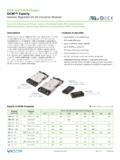
1 Half Brick, DC-DC Converters25 to 100 WattsVI-J00VE-J00VI-J00 DC-DC ConvertersRev 1 of 706/2017 SNRTLCUSCUS Features & Benefits Isolated output Up to 50W/in3 cURus, cT Vus CE Marked Up to 90% efficiency Size: x x (57,9 x 61,0 x 12,7mm) Remote sense and current limit Logic disable Wide range output adjust ZCS power architecture Low noise FM control RoHS compliant (VE verisons) Product HighlightsThe VI-J00 MiniMod family established a new standard in component-level DC-DC converters. This junior size complement to the higher power VI-200 family offers up to 100W of isolated and regulated power in a board mounted package.
2 With thousands of input/output/power combinations, and with a maximum operating temperature rating of 100 C, the MiniMod provides nearly unlimited flexibiliy for power system designers to meet demanding time to market Vicor s zero-current-switching forward converter technology, proven by an installed base of over 8 million units, the MiniMod family combines state of the art power density with the efficiency, low noise and reliability required by next generation power NumberingVI J 6 1 C W FamilySeriesInputOutputGradePowerVI = Non-RoHS J = J00 0 = 12V N = 48V Z = 2V M = 10V K = 40V E = 10 to 100 C 5V < 5V VE = RoHS V = 24V 4 = 72V Y = 1 = 12V 4 = 48V C = 25 to 100 C W = 100W W = 20A1 = 24V T = 110V 0 = 5V P = H = 52V I = 40 to 100 C X = 75W X = 15AW = 24V 5 = 150V X = 2 = 15V F = 72V M = 55 to 100 C Y = 50W Y = 10A 2 = 36V 6 = 300V W = N =
3 D = 85V Z = 25W Z = 5A 3 = 48V 7 = 150/300V V = 3 = 24V B = 95V T = L = 28VR = J = 36 VNote: For additional packaging options, please see page DC-DC Converters Rev 2 of 7 06/2017VI-J00, VE-J00 Converter Specifications(Typical at TBP = 25 C, nominal line and 75% load, unless otherwise specified.)Input SpecificationsMaximum Power Available for VI-Jxx-xxInputOutputVoltageNom. (Range)Low Line75%Max PowerTransient[a]VIN DesignatorsVOUT (10 20)n/a220 XXYYYYYYXXXXXXXXXXXXXX24 (10 36)n/an/aV--YYYYYYYYYYYYYYYYY--------24 (21 32)18361 WWWWWWXXWWWWWWWWWWWWWW24 (18 36)n/an/aWWWWWWWXXWWWWWWWWWWWWWW36 (21 56)18602 YYYYYYYYXXXXXXXXXXX------48 (42 60)36723 WWWWWWXXWWWWWWWWWWWWWW48 (36 76)n/an/aNWWXXXXXXWWWWWWWWWWWWWW72 (55 100)451104 WWWWWWXXWWWWWWWWWWWWWW110 (66 160)n/an/aTWWXXXXXXWWWWWWWWWWWW----150 (100 200)852155 WWWWWWXXWWWWWWWWWWWWWW150 (100 375)n/an/a7 YYYYYYYYXXXXXXXXXXX------300 (200 400)
4 1704256 WWWWWWXXWWWWWWWWWWWWWW[a] Transient voltage for 1 E-GradeVI-J00 C-, I-, M-GradeParameterMinTypMaxMinTypMaxUnitsT est ConditionsInrush charge60 x 10-660 x 10-6100 x 10-6 CoulombsNominal lineInput reflectedripple current pp10%10%IINN ominal line, full loadInput ripple rejection25+20 Log30+20 LogdB120Hz, nominal line20+20 LogdB2400Hz, nominal lineNo load power ()VINVOUT()VINVOUT()VI-J00 DC-DC Converters Rev 3 of 7 06/2017VI-J00, VE-J00 Converter Specifications (Cont.)(Typical at TBP = 25 C, nominal line and 75% load, unless otherwise specified.)[a] 10V to 15V outputs, or V input range have standard trim range 10%.
5 Consult factory for wider trim range. 95V output 50 + 0% trim CharacteristicsControl Pin SpecificationsVI-J00 E-GradeVI-J00 C-, I-, M-GradeParameterMinTypMaxMinTypMaxUnitsT est ConditionsSetpoint accuracy1%2% to HL, 10% to Full LoadLoad/line regulation1% to HL, No Load to 10%Output temperature / COver rated term hoursOutput ripple pp:200100150mV20 MHz bandwidth2V, bandwidth10 95V3% bandwidthTrim range[a]50%110%50%110%VNOMT otal remote sense max. neg. legCurrent limit105%135%105%125%IFULL LOADA utomatic restartShort circuit current105%140%105%130%IFULL LOADA utomatic restartVI-J00 E-GradeVI-J00 C-, I-, M-GradeParameterMinTypMaxMinTypMaxUnitsT est ConditionsGate out impedance5050 OhmsGate in impedance10001000 OhmsGate in high threshold66 VoltsUse open collectorGate in low in low current66mANote: The permissible load current must never be exceeded during normal, abnormal or test conditions.
6 For additional output related application information, please refer to output connections on page DC-DC Converters Rev 4 of 7 06/2017VI-J00, VE-J00 Dielectric Withstand CharacteristicsThermal CharacteristicsMechanical SpecificationsProduct Grade Temperatures[d] No overtemp protection in booster E-GradeVI-J00 C-, I-, M-GradeParameterMinTypMaxMinTypMaxUnitsT est ConditionsInput to output3,0003,000 VRMSB aseplate earthedOutput to baseplate500500 VRMSI nput to baseplate1,5001,500 VRMSVI-J00 E-GradeVI-J00 C-, I-, M-GradeParameterMinTypMaxMinTypMaxUnitsT est ConditionsEfficiency78 88%80 90%Baseplate to C/WattWith Vicor P/N 20267VI-J00 E-GradeVI-J00 C-, I-, M-GradeParameterMinTypMaxMinTypMaxUnitsT est ( ) (92) ( ) ( ) (107) ( )Ounces(Grams)
7 ParameterStorageOperatingUnitsNotesE-20 to +105-10 to + 100 CC-40 to +105-25 to + 100 CI-55 to +105-40 to + 100 CM-65 to +105-55 to + 100 CConverter Specifications (Cont.)(Typical at TBP = 25 C, nominal line and 75% load, unless otherwise specified.)Maximum Capacitance, Rated Output Voltage <5 VMaximum Capacitance, Rated Output Voltage 5 VRated VOUT (V)IOUT Rating (A)CMAX ( F)IOUT Rating (A)CMAX ( F)2 to <3 101500>10 to 2050003 to <5 101000>10 to 205000 Rated VOUT (V)POUT Rating (W)CMAX ( F)POUT Rating (W)CMAX ( F)5 to < 501000>50 to to <10 50400>50 to 10070010 to <28 50400>50 to 100500>28 50150>50 to 100250VI-J00 DC-DC Converters Rev 5 of 7 06/2017VI-J00, VE-J00 Output Connections and ConsiderationsThe permissible load current [e] must never be exceeded during normal, abnormal or test conditions.
8 Converters subject to dynamic loading exceeding 25% of rated current must be reviewed by Vicor Applications Engineering to ensure that the converter will operate dynamic load, light load, or no load conditions, the converter may emit audible noise. Converters that utilize remote sense may require compensation circuitry to offset the phase lag caused by the external output leads and load impedance. Remote Sense leads must be protected for conditions such as lead reversal, noise pickup, open circuit, or excessive output lead resistance between the sense point and the converters output terminals.
9 For applications that may draw more than the rated current, a fast acting electronic circuit breaker must be utilized to protect the converter. Under no circumstance should the rated current be exceeded. Utilizing or testing of current limit or short circuit current will damage the converter. Ensure that the total output capacitance connected to the converter does not exceed the limits on Page products, when not installed in customer units, should be stored in ESD safe packaging in accordance with ANSI/ESD , Protection of Electrical and Electronic Parts, Assemblies and Equipment and should be maintained in a temperature controlled factory/warehouse environment not exposed to outside elements controlled between the temperature ranges of 15 C and 38 C.
10 Humidity shall not be condensing, no minimum humidity when stored in an ESD compliant package.[e] Permissible load current:+OUT+IN IN OUTZero CurrentSwitchingConverterC1aC1bC2aC2bC3F 1 Figure 1 Basic module operation requires fusing, grounding, bypassing capacitors.* See Design Guide & Applications Module OperationNominal Power RatingNominal VOUTC3 ( F) = 400 VIN MinimumVI-J00 DC-DC Converters Rev 6 of 7 06/2017VI-J00, Dia (2) Dia (2) placesSolder plateMatte tin over copperover copper (1,0) Dia (7) Dia (7) placesMatte tin over copperSolder plateover copper BaseProduct IDthis surfaceFunction +In -In +Out Trim Sense OutPin # 1 2 3 4 5 6 7 8 9 FULL R+.
