Transcription of Features and Application - Aero-Electric
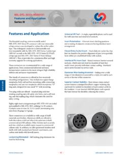
1 MIL-DTL-83723 Series III. Features and Application Bayonet and Threaded Coupling Features and Application Shell Polarization Alternate key/keyway positions pre- vent cross mating of adjacent connectors having same insert MIL-DTL-83723 Series III family offers connectors with arrangement. bayonet and threaded coupling including lanyard-release quick-disconnects. These connectors combine the best Features Closed-Entry Socket Insert Hard dielectric socket face has of MIL-DTL-26500 and NAS 1599 miniature connector lead-in chamfers for positive alignment of pins (even partially specifications. They are intermateable with both bayonet and bent within pre-established limits) with sockets.
2 Threaded 26500 connectors (exception: shell size 8, threaded coupling only) and have the added advantage provided by the Interfacial Pin Insert Seal Raised moisture barriers around rear-release contact retention system. each pin, which mate into lead-in chamfers of hard face sock- et insert, provide individual contact sealing. Interfacial seal is AE833 connectors are widely used on commercial, military never touched by service tools. and aerospace systems requiring general-purpose, miniature cylindrical bayonet or threaded coupling connectors. In Elastomer Wire Sealing Grommet Sealing over a wide addition, Series III threaded connectors with self-locking range of wire diameters is assured by a triple wire seal in each plugs are well suited for engine applications .
3 Cavity at the rear of the connector. This family of connectors (bayonet as well as threaded) is Superior Contact Stability Rear release crimp contact offered in wall mount receptacles as well as jam nut mounted system Features a stamped beryllium-copper retaining clip receptacles which incorporate O ring seals, designed for captivated by molded-in shoulders of each contact cavity in rear panel D hole mounting. the insulator. A rear-inserted M81969 plastic tool expands the tines beyond the shoulder, releasing the contact. Series III bayonet-coupling plugs are available in two designs - with and without RFI grounding. Threaded coupling plugs are offered with and without RFI grounding, self-locking and RFI/self-locking.
4 In addition we offer quick-disconnect (lanyard release) plugs, which mate with threaded receptacles via an adapter. Thirty-one insert arrangements per MIL-STD-1554 are tooled and qualified to MIL-DTL-83723 Series III, utilizing 2 to 61 M39029 contacts. Contacts come in sizes 20, 16 and 12, terminating wire sizes from 24 to 12 gauge. 83723 S III. These connectors are available in wide range of shell materials and finishes. Aluminum shells are offered in electroless nickel, olive drab cadmium and black anodic. Other finishes such as zinc cobalt are available upon request to commercial callouts only. In addition, we offer passivated stainless steel shells with both standard and firewall-rated inserts, and for highly corrosive environments, nickel-aluminum-bronze shells with standard environment-resisting inserts (commercial callouts only).
5 Universal I/R Tool A single, expendable plastic tool is used for both insertion and removal of contacts. 127 MIL-DTL-83723 Series III. Performance Specifications Bayonet and Threaded Coupling Performance Specifications Durability Mated connectors withstand a minimum of 500 mating cycles for bayonet coupling straight plug (M83723/75, Operating Temperature Range 76); 250 mating cycles for bayonet coupling RFI plug Classes A and R: -65 C to +200 C (-85 F to +392 F) (M83723/77, 78); and 250 cycles for all threaded coupling Class W: -65 C to +175 C (-85 F to +347 F) plugs (M83723/86, 87, 91, 92, 95, 96, 97, 98). Classes G and K: -65 C to +200 C (-85 F to +392 F).
6 Classes N and S: -65 C to +200 C (-85 F to +392 F) Shock and Vibration Requirements Wired, mated connectors shall not be damaged, coupling Material and Finish Data (Class) ring shall not loosen, and there shall be no interruption of A aluminum shell, black anodized finish electrical continuity longer than one microsecond when G stainless steel shell, passivated subjected to the following: K stainless steel shell, passivated, firewall R aluminum shell, electroless nickel finish Shock S stainless steel shell, passivated, firewall, and 360 teeth Mated connectors withstand a pulse of approximate half W aluminum shell, olive drab cadmium over nickel base sine wave of 300 G 15 percent magnitude with duration of N stainless steel shell, electrodeposited nickel, firewall, and 3 1 milliseconds applied in three axes.
7 360 teeth Vibration Corrosion Resistance Mated connectors withstand the following vibration levels: Class W withstands 500-hour salt spray. Random vibration per MIL-STD-1344, method 2005, test Class R withstands 48-hour salt spray. condition VI, letter J. Environmental Seal Shielding Effectiveness Wired, mated connectors with specified accessories at- RFI attenuation at the specified frequency meets the require- tached, shall meet the altitude-immersion test specified by ments of MIL-DTL-83723 Series III. MIL-DTL-83723 Series III. RFI shielding effectiveness of mated connectors with RFI backshells is measured in a triaxial radio frequency Fluid Resistance leakage fixture.
8 Connectors resist specified immersions in MIL-PRF-7808. (lubricating oil), MIL-PRF-23699 (lubricating oil), Shell-to-Shell Conductivity (Except class A). MIL-PRF-5606 (hydraulic fluid), M2-V Chevron oil, Coola- With RFI spring fingers, the maximum potential drop nol 25, MIL-DTL-83133 (turbine fuel JP-8), shall not exceed 5 millivolts. MIL-DTL-5624 (turbine fuels JP-4 and JP-5), SAE-AMS1424 Without spring fingers, the maximum potential drop 83723 S III. Type I (defrosting fluid), and other solvents and cleaning shall not exceed 200 millivolts. agents. Voltage Rating Suggested Operating Voltage* Test Voltage Test Voltage Test Voltage Test Voltage (Sea Level) Sea Level 50,000 Ft.
9 70,000 Ft. 110,000 Ft. Service Rating AC (RMS) DC V RMS V RMS V RMS V RMS. I 600 850 1500 500 375 200. II 900 1250 2300 750 500 200. * To be used by designer only as a guide. 128 MIL-DTL-83723 Series III. Part Number Development Bayonet Coupling Military and Aero-Electric Part Number Development Mil. Prefix M83723/ 71 R 12 12 N. Aero Prefix AE833 71 R 12 12 N -340. Shell type 71 = Wall mount receptacle with socket contacts 72 = Wall mount receptacle with pin contacts 73 = Jam nut receptacle with socket contacts 74 = Jam nut receptacle with pin contacts 75 = Straight plug with socket contacts 76 = Straight plug with pin contacts 77 = RFI grounding plug with socket contacts 78 = RFI grounding plug with pin contacts Class (Material and Finish).
10 A = Aluminum shell, black anodized finish (not available in 77 and 78 RFI plugs). G = Stainless stell shell, passivated R = Aluminum shell, electroless nickel finish W = Aluminum shell, olive drab cadmium over electroless nickel finish Shell Size (SS). 8, 10, 12, 14, 16, 18, 20, 22 or 24. Insert Arrangement See pages 148 and 149. Polarization (Keying). N = Normal 6, 7, 8, 9 or Y (Alternate keyed positions, Y is not availabe in SS 8). 1, 2, 3, 4 or 5 (Clocked insert polarizations within normally keyed shell, not approved for new design, n/a in SS 8). Modification (applies to Aero part numbers only). 01 = Less contacts (Part is bagged and tagged, but not marked with 01).


