Transcription of Features and Application - Aero-Electric
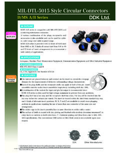
1 MIL-DTL- 5015 /AS50151. Features and Application Series III. Features and Application Universal I/R Tool A single, expendable plastic tool is used for both insertion and removal of contacts. The threaded coupling, environmentally sealed Insert Polarization Alternate insert clocking positions MIL-DTL- 5015 Series III connector with rear-removable aid in mating of adjacent connectors having identical insert crimp contacts was developed to replace the earlier solder arrangement. type. This redesigned connector is intermateable and intermountable with the MIL-DTL- 5015 Series I solder type Closed-Entry Socket Insert Hard dielectric socket face has (MS310*) as well as the MIL-DTL- 83723 Series II (USAF) lead-in chamfers for positive alignment of pins (even partially crimp type and MIL-DTL- 5015 Series II Front Release bent within pre-established limits) with sockets.
2 (MS340*). Thus, it provides for a minimum effort and high economy upgrade for existing applications . Interfacial Pin Insert Seal Raised moisture barriers around each pin, which mate into lead-in chamfers of hard face These connectors are recommended for a wide range of socket insert, provide individual contact sealing. Interfacial applications , from commercial/industrial and mass seal is never touched by service tools. transportation systems to the most stringent high reliability defense and aerospace requirements. Elastomer Wire Sealing Grommet Sealing over a wide range of wire diameters is assured by a triple wire seal in each This family of connectors is offered in four receptacle cavity at the rear of the connector. mounting configurations. They include two square flange receptacles, both wall and box mounting; cable connecting Superior Contact Stability Rear release crimp contact 5015 S III.
3 Receptacles; and jam nut receptacles which incorporate O system Features a stamped beryllium-copper retaining clip ring seals, designed for rear panel D hole mounting. captivated by molded-in shoulders of each contact cavity in the insulator. A rear-inserted M81969 plastic tool expands Two plug styles are offered - standard plug with free the tines beyond the shoulder, releasing the contact. rotating coupling nut with safety wire holes, and a self-lock- ing, anti-decoupling plug, which eliminates the need for safety wiring. Eighty-eight insert arrangements per MIL-STD-1651 are tooled and qualified to MIL-DTL- 5015 , utilizing 1 to 85 contacts. Contacts come in sizes 16, 12, 8, 4 and 0, terminating wire sizes from 20 gauge to 0 gauge. These connectors are available in wide range of shell materials and finishes. Aluminum shells are offered in both electroless nickel and olive drab cadmium to both commercial and MS callouts.
4 Other finishes such as anodic and zinc cobalt are available upon request to commercial callouts only. In addition, we offer passivated stainless steel shells with both standard and firewall-rated inserts, and carbon steel shells with firewall inserts. Lockwiring Eliminated Self-locking plug eliminates the need for lockwiring. 63 MIL-DTL- 5015 /AS50151. Performance Specifications MS345*/AE55*. Performance Specifications Shock and Vibration Requirements Wired, mated connectors shall not be damaged, coupling ring shall not loosen, and there shall be no interruption of Operating Temperature Range electrical continuity longer than 10 microseconds when Classes KS and LS: -55 C to +200 C (-67 F to +392 F) subjected to the following: Classes KT and W: -55 C to +175 C (-67 F to +347 F). Class L: -55 C to +200 C (-67 F to +392 F) Shock Class A*: -55 C to +200 C (-67 F to +392 F) Mated connectors withstand a pulse of approximate half sine wave of 50 G magnitude with duration of 11 milliseconds Material and Finish Data (Class) applied in three axes per MIL-STD-1344, method 2004, KT carbon steel shell, olive drab cadmium, firewall test condition A.
5 KS stainless steel shell, passivated, firewall L aluminum shell, electroless nickel finish Vibration LS stainless steel shell, passivated Mated connectors withstand the following vibration levels: W aluminum shell, olive drab cadmium over nickel base Random vibration per MIL-STD-1344, method 2005, A* aluminum shell, black anodized finish and test condition VI, letter J. Corrosion Resistance Shell-to-Shell Conductivity Classes KS and LS withstand 1,000-hour salt spray. Maximum potential drop shall not exceed: Class KT withstands 96-hour salt spray. Class W = 5 millivolts Class L withstands 96-hour salt spray. All other classes (except A*) = 50 millivolts 5015 S III. Class W withstands 1,000-hour salt spray. Fluid Resistance Environmental Seal Connectors resist specified immersions in MIL-PRF-7808. Wired, mated connectors with specified accessories (lubricating oil), MIL-PRF-23699 (lubricating oil), attached, shall meet the altitude-immersion test specified MIL-PRF-5606 (hydraulic fluid), M2-V Chevron oil, in MIL-DTL- 5015 .
6 Coolanol 25, MIL-DTL-83133 (turbine fuel JP-8), MIL-DTL-5624 (turbine fuels JP-4 and JP-5), SAE-AMS1424. Durability Type I (defrosting fluid), and other solvents and cleaning Minimum of 100 mating cycles agents. Voltage Rating Maximum Operating Voltage** Test Voltage Test Voltage Test Voltage Test Voltage (Sea Level) Sea Level 50,000 Ft 70,000 Ft. 110,000 Ft. Service Rating AC (RMS) DC V RMS V RMS V RMS V RMS. Inst. 200 250 1000 400 260 200. A 500 700 2000 600 360 200. D 900 1250 2800 675 400 200. E 1250 1750 3500 750 440 200. B 1750 2450 4500 825 480 200. C 3000 4200 7000 975 560 200. * Not MS approved, available to Aero-Electric part number only. **To be used by designer only as a guide. 64 MIL-DTL- 5015 Series III /AS50151. Part Number Development Rear Release Military and Aero-Electric Part Number Development Mil. Prefix MS34 50 L 14S - 5 P X.
7 Aero Prefix AE5 50 L 14S - 5 P X -340. Shell Type 50 = Wall mount receptacle 51 = Cable connecting receptacle 52 = Box mount receptacle 54 = Jam nut receptacle 56 = Straight plug 59 = Self-locking plug Class (Material and Finish). A = Aluminum shell, black anodized finish (Aero part number only). KS = Stainless steel shell, passivated, firewall (n/a in MS3451, MS3452, MS3454). KT = Carbon steel shell, cadmium finish, firewall (n/a in MS3451, MS3452, MS3454). LS = Stainless steel shell, passivated L = Aluminum shell, electroless nickel finish W = Aluminum shell, olive drab cadmium over electroless nickel base Shell Size 8S, 10S, 10SL, 12, 12S, 14, 14S, 16, 16S, 18, 20, 22, 24, 28, 32, 36 or 40. 5015 S III. Insert Arrangement See pages 82 thru 87. Contact Style P = Pin S = Socket A = Pin connector less pins (with intent to use non-std contact).
8 B = Socket connector less sockets (with intent to use non-std contacts). Polarization N = Normal (not included in part number). W, X, Y or Z = Alternate insert polarizations (see pages 77 thu 81 for position availability). Modification (applies to Aero part numbers only). 01 = Less contacts (is not marked on the part). 340 = Connector kitted with M85049/31-XXX E-nut 341 = Connector kitted with M85049/52-1-XXX straight clamp 342 = Connector kitted with M85049/51-1-XXX right angle clamp Consult factory for other modifications Note 1: Each connector is furnished with contacts unless Note 2: KS and KT firewall classes are only available to ordered less contacts (L/C) as follows: One spare contact for Military part numbers for shell types MS3450, MS3456. inserts requiring 2 to 26 of each contact and two spares for and MS3459. KS and KT classes are available to Aero inserts with 27 or more of each size, and a minimum of one callouts for AE551 and 554, but not for AE552 (box mount sealing plug up to 15% of the number contacts.)
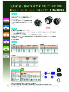
9 No spares or receptacle). seal plugs are provided with one contact layouts. No spares or seal plugs for contact sizes 0 and 4 are provided. For Note 3: Proper part number marking has no 0 in front contact size 8, no contact spares are provided, but seal plugs of single digit (numeric) shell size (8S) and no 0 in front of are included. In addition, one insertion/removal tool of each single digit layout. Examples: J MS3450W8S-1S and size is included. J MS3450W24-2PW. Please note that J or JAN marking is required immediately in front of MS part number. 65 MS3450 per AS34501. Wall Mount Receptacle AE550. Threaded Coupling, Crimp Removable, Rear Release G L. MAX. F MIN FULL THREAD. POLARIZING KEY D B .290( ) FOR 8S-24..467( ) FOR 28-40. A MATING THREAD..340( )..130( ). FOR 8,4, AND 0 CONTACTS. GROMMET. EXTENSION .190( )..130( ). FOR 16 AND 12 CONTACTS.
10 3 ACCESSORY TEETH. J ACCESSORY THREAD. 4x H HOLES. BLUE COLOR BANDS. Page 65 Completed Part Number 5015 S III. Page 75 Contacts, Sealing Plugs and Tools Pages 82 87 Insert Arrangements Note 1: L max is same as L max for AE551 on next page. Page 64 Performance Specifications Pages 77 81 Insert Availability and Contact Information Note 2: Maximum grommet is same as E max for Page 77 Polarization AE551 on next page. A B D F G H J. Mating Classes L, LS, W Classes KS, KT Accessory Thread +.031 +.79 +.010 +.25 +.010 +.25 Thread Shell Class 2A .015 .38 (TP) .031 .79 Class 2A. Size inch mm inch mm inch mm inch mm inch mm inch mm 8S 1/2-28 UNEF .083 .562 .594 .875 .120 .150 1/2-20 UNF. 10S 5/8-24 UNEF .083 .562 .719 .120 .150 5/8-24 UNEF. 10SL 5/8-24 UNEF .083 .562 .719 .120 .150 5/8-24 UNEF. 12 3/4-20 UNEF .083 .750 .812 .120 .150 3/4-20 UNEF.