Transcription of Features - pottersignal.com
1 PAGE 1 OF 4 Potter Electric Signal Company, LLC St. Louis, MO Phone: 800-325-3936 C 6/17S-24 & HS-24 Selectable Candela Strobe & Horn/StrobesS3247 Features 24 VDC units have field selectable candela options of 15, 30, 60, 75 & 110 Super-Slide Bracket - Ease of Supervision Testing Checkmate - Instant Voltage Verification Synchronize strobe and/or horn with AVSM Control Module Prewire entire system, install mounting bracket, then install signals Documented lower installation and operating costs Switch selection for high or low dBA Switch for chime, whoop, mechanical and 2400Hz tone Tamperproof re-entrant style grill Switch for continuous or temporal 3 tone (not available on whoop tone) Silence audible while visual appliance will remain flashing (for use in accepted jurisdictions)
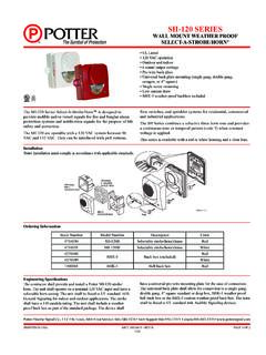
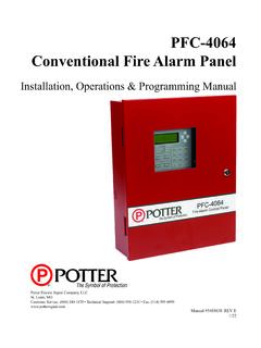
2 Faceplate available in red or off-whiteDescriptionThe S-24/HS-24 Series is a low profile strobe and horn/strobe combination that offers dependable audible and visual alarms and the absolute lowest current available. The S-24 & HS-24 Series 24 VDC offers tamperproof field selectable candela options of 15, 30, 60, 75, and 110 candela. The Strobe and Horn/Strobe offers a continuous or sync temporal three in 2400Hz and mechanical tone, a chime and whoop tone. All tones are easy for the professional to change in the field by the use of switches. The S-24 & HS-24 Series has a minimal operating current and has a minimum flash rate of 1Hz regardless of input Series is shipped with a standard 4 metal mounting plate which incorporates the popular Super-Slide feature that allows the installer to easily test for supervision.
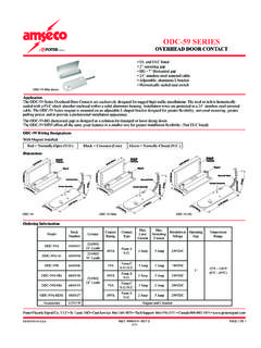
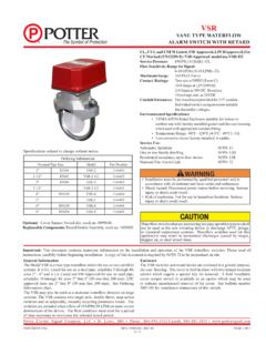
3 The product also Features a locking mechanism which secures the product to the bracket without any screws S-24/HS-24 also Features the patented Checkmate - Instant Voltage Verification feature which allows the installer to check the voltage drop draw and match it to the S-24 & HS-24 Series appliances are ANSI/UL 464 and ANSI/UL 1971, listed for use with fire protective systems and are warranted for three years from date of Specifications Mounting OptionsSingle or Double gang, 4 square box, and AVBB surface mount back boxTerminalsScrew-Clamp TypeWire Gauge18 12 AWGO perating Temp32 F 120 F (0 49 C)DimensionsHeight 5 Width Depth Shipping lbs PAGE 2 OF 4 Potter Electric Signal Company, LLC St. Louis, MO Phone: 800-325-3936 & HS-24 Selectable Candela Strobe & Horn/Strobes8830054-REV C 6/17 TONESWITCH POSITION345 Mechanical Temporal 3 ONONONM echanical ContinuousOFFONON2400 Hz Temporal 3 ONOFFON2400 Hz ContinuousOFFOFFONC hime Temporal 3 ONONOFFC hime ContinuousOFFONOFFW hoopONOFFOFFW hoopOFFOFFOFFNOTE: Switch Positions 1 The and 2 in the OFF position to select isolated horn and strobe power inputs Switch Position 6 ON = HIGH dBA Switch Position 6 OFF = LOW dBACandela selection slider switch.
4 Depress center and slide switch todesired brightness off pin and insert intohole at the bottom of theselector to lock candela setting. Signal must beremoved from bracket andpin pushed forward frombackside out of hole tochange access holes are provided in the back of the terminal block to allow the voltage to be measured directly without removing the device. Typically this would be done at the end of the line to confirm design criteria. Most measure-ments will be taken using the S+ and S- locations although access is provided to other locations. NOTE: Care should be taken to not short the test Slide Mounting BracketAllows the installer to pre-wire the system, test for system supervision, remove the signal head until occupancy, switch out signals without changing mounting brackets and has locking edge connector for snap-in-place remove bezel, grip both sides of bezel and pull in a downward and outward SelectionCheckmate - Instant Voltage VerificationSwitch Locations PAGE 3 OF 4 Potter Electric Signal Company, LLC St.
5 Louis, MO Phone: 800-325-3936 & HS-24 Selectable Candela Strobe & Horn/Strobes8830054-REV C 6/17S-24 24 VDC Selectable Candela, Low Profile Evacuation StrobeModel NumberPart NumberNominal VoltageCandela (ANSI/UL 1971)S-24WR489001024 VDC15, 30, 60, 75, 110S-24WW489001124 VDC15, 30, 60, 75, 110HS-24 24 VDC Selectable Candela, Low Profile Evacuation StrobeModel NumberPart NumberNominal VoltageCandela (ANSI/UL 1971)Reverberant dBA at 10 ft, per ANSI/UL 464In Anechoic Room at 10 ftHS-24WR489003024 VDC15, 30, 60, 75, 11062-82100HS-24WW489003124 VDC15, 30, 60, 75, 11062-82100S-24 & HS 24 Strobe Current Ratings24 VDC (16 - 33 Volts)Candela24 VDCUL Max15 cd30 mA42 mA30 cd35 mA58 mA60 cd66 mA97 mA75 cd80 mA116 mA110 cd103 mA161 mAModel Designations:W = Wall mountR = Red Faceplate W=White FaceplateAll units are available in plain (no lettering)Plain units are non-returnable.
6 ALERT bezel available for order. AGENT bezel available for order. S-24 & HS-24 Horn RatingsHorn ModeHorn Decibel LevelsHorn Current RatingsMinimum SPL at 10 ft, per ANSI/UL 464 (HIGH)Minimum SPL at 10 ft, per ANSI/UL 464 (LOW)Regulated 24 VDC Max Operating @ High Setting (mA)Temp 3 (2400 Hz)78 dBA71* dBA28 mATemp 3 (Mechanical)76 dBA70* dBA25 mATemp 3 (Chime)70* dBA66* dBA15 mAContinuous (2400 Hz)81 dBA74* dBA28 mAContinuous (Mechanical)80 dBA72* dBA25 mAContinuous (Chime)70* dBA66* dBA15 mAWhoop82 dBA69* dBA56 mANOTES: For nominal and peak current across ANSI/UL regulated voltage range for filtered DC power and unfiltered (FWR [Full Wave Rectified]) power see installation manual. Potter does not recommend using a coded or pulsing signaling circuit with any of our strobe products.
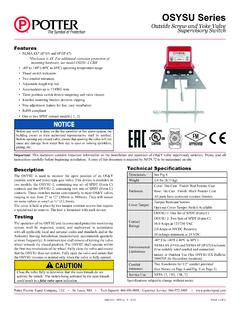
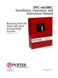
7 The sound output for the temporal 3 tone is rated lower since the time the horn is off is averaged into the sound output rating. While the horn is producing a tone in the temporal 3 mode its sound pressure is the same as the continuous mode.* Operating the horn in this mode at this voltage will result in not meeting the minimum ANSI/UL 464 reverberant sound level required for public mode fire protection service. These settings are acceptable only for private mode fire alarm use. Use the high dBA setting for public mode application (not applicable when using the chime tone. The chime tone is always private mode). PAGE 4 OF 4 Potter Electric Signal Company, LLC St. Louis, MO Phone: 800-325-3936 & HS-24 Selectable Candela Strobe & Horn/Strobes8830054-REV C 6/17S-24 & HS-24 Series Wiring DiagramNotes:All strobes are designed to flash as specified with continuous applied voltage.
8 Strobes should not be used on coded or pulsing signaling circuits. However, use of the Potter AVSM control module or Gentex synchronization protocol is permitted to synchronize the strobe, horn, and/or mute the horn. FOR SYNCHRONIZATION WIRING INFORMATION, REFERENCE AVSM CONTROL MODULE DATA SHEET (8830050) AND/OR AVSM CONTROL MODULE MANUAL FOR SYNCHRONIZATION MODULE WIRING DIAGRAMS. AVSM CONTROL MODULE DATA SHEET AND MANUAL CAN BE OBTAINED AT OR CALL POTTER ELECTRIC TECHNICAL SUPPORT AT 1-866-956-1211 Architect & Engineering SpecificationsThe audible and/or visible signal shall be Potter S-24 strobe and Potter HS-24 horn/strobe Series or approved equal and shall be listed by Underwriters Laboratories, Inc. per ANSI/UL 1971 and/or ANSI/UL 464. The notification appliance shall also be listed with Factory Mutual Listing Service (FM) and the California State Fire Marshal (CSFM).
9 The notification appliance (combination audible/visible) shall produce a peak sound output of 100dBA or greater at 24 VDC as measured in an anechoic chamber. The signaling appliance shall also have the capability to silence the audible signal while leaving the visible signal energized with the use of a single pair of power wires. Additionally, the user shall be able to select either continuous or temporal tone output with the temporal signal having the ability to be shall be capable of being installed so that any unauthorized attempt to change the candela setting will result in a trouble signal at the fire alarm control audible/visible and visible signaling appliance shall also maintain a minimum flash rate of 1Hz or up to 2Hz regardless of power input voltage. The strobe appliance shall have an operating current of 42mA or less at 24 VDC for the 15Cd strobe appliance shall be polarized to allow for electrical supervision of the system wiring.
10 The unit shall be provided with a mounting bracket with terminals and barriers for input/output wiring and be able to mount to a single gang or double gang box or double workbox without the use of an adapter plate. The unit shall have an input voltage range of 16-33 volts with either direct current or full wave rectified power for 24 VDC appliance shall be capable of testing supervision without disconnecting wires, verify voltage without removing unit and be capable of mounting to a surface back box.