Transcription of February 2004 Rosemount 144 PC-Programmable …
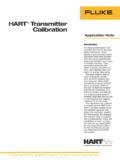
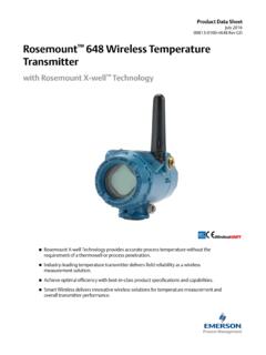
1 Product Data Sheet 00813-0100-4796, Rev DB February 2004 Model 144H Rosemount 144 PC-Programmable Temperature transmitter Provides an installation-ready solution for temperature monitoring applications using Complete Point Solutions (CPS) Increases measurement accuracy and reliability over sensors wired direct Accepts 2- and 3-wire Pt 100 and Ni 100 RTD sensor inputs Reduces overall installed costs compared to wiring sensors direct Is configurable using the Rosemount 144C Configuration Interface and a standard PC Content The Rosemount 144 .. page 2 Specifications .. page 3 Hazardous Locations Certifications.. page 4 Dimensional Drawings.. page 5 Ordering Infrmation .. page 7 Product Data Sheet Model 144H 00813-0100-4796, Rev DB February 2004 The Rosemount 144 PC-Programmable Temperature TransmitterThe Rosemount 144 is a low cost temperature transmitter used for RTD-only sensor measurement in monitoring applications.
2 Compared to wiring direct, the Rosemount 144 will save money in cabling and installation costs while delivering improved measurement accuracy and reliability. INSTALLATION READY SOLUTIONS The Rosemount 144 is part of the Complete Point Solutions (CPS) program. CPS guarantees that the transmitter , sensor, extension, and thermowell will be shipped from the factory as an installation-ready assembly. INCREASED PERFORMANCE The Rosemount 144 offers better measurement accuracy and improved reliability over wiring a temperature sensor directly back to the DCS. Also, the 4-20 mA signal from a transmitter is not as sensitive to noise as a long run of sensor wire. FLEXIBILITY. The Rosemount 144 is compatible with 2- and 3-wire nickel and platinum RTDs, as well as ohm inputs. LOW INSTALLED COST The Rosemount 144 reduces overall installation costs when compared to wiring sensors direct.
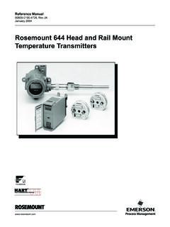
3 In addition, the 144 can eliminate the use of expensive extension wires and multiplexers. programmable The Rosemount 144C Configuration Interface consists of a programmer, cables, and configuration software. The configuration software, when used in conjunction with the interface, provides the tools necessary to select the sensor type, sensor range, and sensor error action in addition to many other options. 2 Product Data Sheet 00813-0100-4796, Rev DB February 2004 Model 144H SpecificationsFUNCTIONAL Supply Voltage DC Standard: to 35 V Intrinsic Safety: to 28 V Minimum Voltage Across Terminals 8 V dc Turn-on Time Performance within specification less than minutes after power is applied to the transmitter Isolation No input to output isolation Communication Interface Rosemount 144C Configuration Interface software and hardware Calibration Temperature 20 C to 28 C (68 F to F).
4 Temperature Coefficient (spans greater than 100 C). Less than of configured span / C. Temperature Coefficient (spans less than 100 C) C / Cambient Ambient Temperature Limits Operating: 40 to 85 C ( 40 F to 185 F) Humidity Limits 0 to 95% relative humidity, non-condensing Maximum Offset 50% of selected maximum value recommended NOTE In order to meet specification, the minimum temperature value of span ( C) must be less than or equal to 50% of the maximum temperature in the span. For example, a span of 50 to 100 C is recommended but a span of 75 to 100 C is not recommended. Maximum Cable Resistance Per Wire 10 Sensor Current < I < mA Linear Resistance Input Measurement Range: 0 to 10 K Minimum Measurement Span: 30 Output Signal Range: 4 20 mA Update 13 milliseconds Load Resistance ( ): (V supply - 8 V) A Load Stability < of configured span 100 Alarm Levels programmable : to 4 mA downscale 20 to 23 mA upscaleNAMUR NE43 Upscale: 21 I 23 mANAMUR NE43 Downscale: I mAInput l) 0 k l) ) (1) ) ) 30 Pt 100 Ni 100 Linear Resistance Min.
5 Va ue 200 C ( 328 F) 60 C ( 70 FMax. Va ue 850 C (1562 F250 C (482 F10 kMin. Span25 C (45 F25 C (45 F(1) Recommended minimum span (1) C F 25 45 25 45 30 Sensor Options Recommended Minimum Span2-, 3-wire RTDs Pt 100 (a = ) Ni 100 Linear Resistance (1)No minimum or maximum span restrictions within the input ranges. Recommended minimum span will hold noise within accuracy specification with damping at zero seconds. PERFORMANCE Accuracy Sensor Options Accuracy 2-, 3-wire RTDs Pt 100 (a = ) of span or C, whichever is greater Ni 100 of span or C, whichever is greater Linear Resistance of span or , whichever is greater programmable Response Time (Damping) to 60 seconds Linearity Error Less than of configured span Effect of Supply Voltage Change Less than/equal to of configured span V dc EMC-Immunity Influence Less than of configured span Improved EMC Immunity NAMUR NE21 A criteria for burst < 1% of configured span Vibration IEC 68 2 6 Test FC Lloyd s Specifications No.)))))
6 1 4 g / (2 to 100 Hz) Effect of Sensor Cable Resistance (3-wire) Less than / . Equal in each lead 3 Product Data Sheet Model 144H 00813-0100-4796, Rev DB February 2004 Product Certifications Approved Manufacturing Locations Emerson Process Management Rosemount Division Chanhassen, Minnesota, USA Rosemount Temperature GmbH Germany Emerson Process Management Asia Pacific Singapore European Union Directive Information The EC declaration of conformity for all applicable European directives for this product can be found on the Rosemount website at A hard copy may be obtained by contacting our local sales representative. ATEX Directive (94/9/EC) Rosemount Inc. complies with the ATEX Directive. Electro Magnetic Compatibility (EMC) (89/336/EEC) 144 Temperature transmitter and 144C Configuration Unit EN 50081-1: 1992; EN 50082-2:1995; Hazardous Locations Certificates North American Certifications Factory Mutual (FM) Approvals K5 Combination Factory Mutual Intrinsically safe and Explosion-proof Approvals Intrinsically Safe for Class I, Division 1; Groups A, B, C, D.
7 Non-incendive for Class I, Division 2, Groups A, B, C, D when installed in accordance with Rosemount Installation Drawing 00144-0110. Ambient temperature limits are between 40 and 85 C. FM Entity Parameters are listed on the installation drawing (00144-0110) identified on the transmitter approval label. Explosion Proof for Class I, Division 1; Groups B, C, D. Dust ignition proof for Class II, Division 1, Groups E, F, and G. Dust ignition proof for Class III, Division 1 hazardous locations when installed in accordance with Rosemount drawing 00144-0130. A conduit seal is not required for compliance with NEC 501-5a(1). T5 (Tamb = 40 to 85 C) NOTE Approval K5 is only available with enclosure codes J5 or J6. Canadian Standards Association (CSA) Approvals C6 Combination of CSA Intrinsically Safe, Nonincendive, and Explosion-Proof: Explosion-Proof for Class I, Division 1, Groups B, C, and D.
8 Dust-ignition proof for Class II, Division 1, Groups E, F, and G. Dust-ignition proof for Class III, Division 1 hazardous locations when installed in accordance with Rosemount Drawing 00144-0140 factory sealed. Suitable for Class I, Division 2, Groups A, B, C, and D. Intrinsically Safe for Class 1, Division 1, Groups A, B, C, and D when installed per Rosemount drawing 00144-0120. Temperature codes: T4 (Tamb = 40 to 85 C); T6 (Tamb = 40 to 60 C)NOTE Approval C6 is only available with enclosure codes J5 or J6. European Certifications CENELEC ATEX Approvals I1 Intrinsically Safe Certification DEMKO 00 ATEX 129255 ATEX Marking: II 1 GEEx ia IIC T6 (Tamb = 40 to 60 C)EEx ia IIC T4 (Tamb = 40 to 85 C)Entity Parameters: Ui = 28 VDC, Ii = 120 mA, Li = 10 H, Ci = 1nF, P= Directives: ATEX: 94/9/ECEMC: 89/336 EECS pecial Conditions for Safe Use (x):1.
9 For correct use and installation the manufacture s manual must be followed. 2. The apparatus must be installed in an enclosure with an Ingress Protection of at least IP20. 3. The terminals 1 and 2 of the equipment have to be electrically connected to a barrier located in the non-hazardous area. 4. The transmitter may only be used with transducers complying with Simple Apparatus according to EN 50020 Clause ED Flameproof Certification KEMA 99 ATEX 8715 ATEX Marking: II 2 GEEx d IIC T6 (Tamb = 40 to 65 C)Maximum Input Voltage: VDirectives: ATEX: 94/9/EC NOTE Only available with enclosure codes J5 or J6. Combination Certifications KCCombination Factory Mutual/CSA Intrinsically Safe Approval Factory Mutual- Intrinsically Safe for Class I, II, III: Div. 1, Groups A, B, C, D. Non-incendive for Class I, Division 2, Groups A,B,C,D, when installed in accordance with Rosemount Installation Drawing 00144-0110.
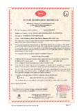
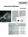
10 Ambient temperature limits are between -40 C and 85 C. FM Entity Parameters are listed on the installation drawing. CSA- Intrinsically Safe for Class I, Division 1, Groups A, B, C, D when connected in accordance with Rosemount Installation Drawing 00144-0120. T4 ( 40 C Ta 85 C), T6 ( 40 C Ta 60 C). 4 Product Data Sheet00813-0100-4796, Rev DBFebruary 20045 Model 144 HDimensional DrawingsRosemount 144 Top ViewRosemount 144 Side ViewDimensions are in millimeters (inches)Remote or Integral Mount(1)(1) The Rosemount 144 remote or integral mount is to be ordered through the 144 model Mount(2)(2) The Rosemount 144 integral mount is to be ordered through the sensor model Universal Head (option code J5 or J6)Integral DIN Style Sensor Connection HeadNote: A U Bolt is shipped with each Universal Head unless assembly option code X1, X2 or X3 is ordered.