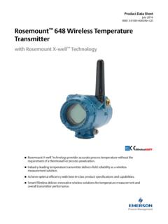
Transcription of Rosemount 644 Head and Rail Mount Temperature …
1 Manual 00809-0100-4728, Rev JAJanuary 2004 Rosemount 644 Head and Rail Mount Temperature TransmittersReference Manual 00809-0100-4728, Rev JAJanuary 2004 Rosemount 644 Temperature TransmittersRosemount 644 Smart Temperature Transmitters may be protected by one or more Patents pending. Other foreign patents 644 Hardware RevisionHART Device RevisionHART Communicator Field Device RevisionFOUNDATION fieldbus Hardware RevisionFOUNDATION fieldbus Device v6, DD v151 NOTICERead this manual before working with the product. For personal and system safety, and for optimum product performance, make sure to thoroughly understand the contents before installing, using, or maintaining this United States has two toll-free assistance numbers and one international Central1-800-999-9307 (7:00 to 7:00 CST)National Response Center1-800-654-7768 (24 hours a day)Equipment service needsInternational1-(952) 906-8888 The products described in this document are NOT designed for nuclear-qualified applications.
2 Using non-nuclear qualified products in applications that require nuclear-qualified hardware or products may cause inaccurate readings. For information on Rosemount nuclear-qualified products, contact a Emerson Process Management Sales Manual 00809-0100-4728, Rev JAJanuary 2004 Rosemount of ContentsSECTION 1 IntroductionSafety Messages .. 1-1 Warnings .. 1-1 Overview .. 1-2 Manual .. 1-2 transmitter .. 1-2 Considerations.. 1-3 General .. 1-3 Commissioning .. 1-3 Mechanical .. 1-3 Electrical .. 1-3 Environmental.. 1-3 Return of Materials .. 1-4 SECTION 2 InstallationSafety Messages .. 2-1 Warnings .. 2-1 Mounting .. 2-3 Installation .. 2-4 Typical European Installation .. 2-4 Typical North American Installation.
3 2-5 LCD Display Installation .. 2-8 Multichannel Installations (HART) .. 2-9 Wiring.. 2-9 Sensor Connections .. 2-11 Power Supply.. 2-13 Ground the transmitter .. 2-14 SECTION 3 HART ConfigurationOverview .. 3-1 Safety Messages .. 3-1 Warnings .. 3-1 Surges/Transients .. 3-2 Commissioning .. 3-2 Setting the Loop to Manual.. 3-2 Failure Mode.. 3-2 Changing Switch Positions .. 3-3 HART Communicator.. 3-3 Configuration .. 3-3 HART Menu Tree .. 3-4 Fast Key Sequence .. 3-5 AMS .. 3-6 Apply AMS Changes .. 3-6 Review Configuration Data .. 3-7 Check Output .. 3-7 Configuration .. 3-7 Reference Manual00809-0100-4728, Rev JAJanuary 2004 Rosemount 644 TOC-2 Information Variables .. 3-12 Diagnostics and Service.
4 3-13 Multidrop Communication .. 3-18 Operation and Maintenance .. 3-19 Calibration .. 3-19 Hardware .. 3-24 Diagnostic Messages .. 3-24 SECTION 4 Foundation Fieldbus ConfigurationOverview .. 4-1 Safety Messages .. 4-1 Warnings .. 4-1 General Block Information .. 4-2 Device Description .. 4-2 Node Address .. 4-2 Modes.. 4-2 Link Active Scheduler .. 4-3 Block Installation.. 4-3 Capabilities .. 4-4 Foundation fieldbus function blocks.. 4-4 Resource Block .. 4-5 Sensor Transducer Block .. 4-9 Analog Input (AI) Function Block .. 4-9 LCD Transducer Block .. 4-13 Operation and Maintenance .. 4-14 Overview.. 4-14 Troubleshooting Guides .. 4-15 Sensor Transducer Block .. 4-17 Analog Input (AI) Function Block.
5 4-20 Resource Block .. 4-22 LCD Transducer block .. 4-23 APPENDIX ASpecifications and Reference DataHART and Foundation Fieldbus Specifications .. A-1 Functional .. A-1 Physical .. A-2 Performance .. A-3 Foundation Fieldbus Specifications .. A-44 20 mA / HART Specifications .. A-6 Dimensional Drawings .. A-10 Ordering Information .. A-12 Additional Information .. A-14 Tagging.. A-14 Considerations .. A-14 Configuration .. A-15 Stainless Steel Housing.. A-16 Dimensional Drawings .. A-17 APPENDIX BProduct CertificationsApproved Manufacturing Locations.. B-1 European Union Directive Information.. B-1 Hazardous Locations Certificates .. B-2 Rosemount 644 with Foundation Fieldbus .. B-2 Rosemount 644 with HART.
6 B-5 Installation Drawings .. B-8 Reference Manual 00809-0100-4728, Rev JAJanuary 2004 TOC-3 Rosemount 644 APPENDIX CFoundation Fieldbus Block InformationBasic Setup .. C-1 Resource Block .. C-1 Parameters and Descriptions .. C-2 Sensor Transducer Block .. C-5 Parameters and Descriptions .. C-5 Analog Input (AI) Function Block .. C-8AI Parameter Table .. C-9 LCD Transducer Block.. C-12 PID Block .. C-13 Reference Manual00809-0100-4728, Rev JAJanuary 2004 Rosemount 644 TOC-4 Reference Manual 00809-0100-4728, Rev JAJanuary 2004 Rosemount 1 IntroductionSafety Messages .. page 1-1 Overview .. page 1-2 Considerations .. page 1-3 Return of Materials .. page 1-4 SAFETY MESSAGESI nstructions and procedures in this section may require special precautions to ensure the safety of the personnel performing the operations.
7 Information that potentially raises safety issues is indicated by a warning symbol ( ). Please refer to the following safety messages before performing an operation preceded by this to follow these installation guidelines could result in death orserious injury. Make sure only qualified personnel perform the could result in death or serious injury. Do not remove the connection head cover in explosive atmospheres when the circuit is live. Before connecting HART or FOUNDATION fieldbus in an explosive atmosphere, make sure the instruments in the loop are installed in accordance with intrinsically safe or non-intrinsic field wiring practices. Verify that the operating atmosphere of the transmitter is consistent with the appropriate hazardous locations certifications.
8 All connection head covers must be fully engaged to meet explosion-proof leaks could result in death or serious injury. Do not remove the thermowell while in operation. Install and tighten thermowells and sensors before applying pressureElectrical shock could cause death or serious injury. Use extreme caution when making contact with the leads and Manual00809-0100-4728, Rev JAJanuary 2004 Rosemount 6441-2 OVERVIEWM anualThis manual is designed to assist in the installation, operation, and maintenance of Rosemount 644 head Mount and 644 rail 1: Introduction transmitter and Manual Overview Considerations Return of MaterialSection 2: Installation Mounting Installation Wiring Power Supply CommissioningSection 3: HART Configuration Rosemount HART Communicator Configuration Multidrop CommunicationSection 4: FOUNDATION Fieldbus Configuration Calibration Hardware Maintenance Diagnostic MessagingAppendix A.
9 Specifications and Reference Data Specifications Dimensional drawings Ordering Information Biotechnology, Pharmaceutical Industries, and Sanitary ApplicationsAppendix B: Approvals Product Certifications Installation DrawingsAppendix C: Foundation Fieldbus Block Information Information regarding the Function BlocksTransmitter Features of the Rosemount 644 include: Accepts inputs from a wide variety of sensors Configuration using HART protocol or FOUNDATION fieldbus Electronics that are completely encapsulated in epoxy and enclosed in a metal housing, making the transmitter extremely durable and ensuring long-term reliability A compact size and two housing options allowing mounting flexibility for the control room or the fieldReference Manual 00809-0100-4728, Rev JAJanuary 20041-3 Rosemount 644 Refer to the following literature for a full range of compatible connection heads, sensors, and thermowells provided by Emerson Process Management.
10 Temperature Sensors and Assemblies Product Data Sheet, Volume 1 (document number 00813-0100-2654) Temperature Sensors and Assemblies Product Data Sheet, Volume 2 (document number 00813-0200-2654) CONSIDERATIONSG eneralElectrical Temperature sensors such as RTDs and thermocouples produce low-level signals proportional to their sensed Temperature . The 644 converts the low-level sensor signal to a standard 4 20 mA dc, digital HART, or digital Foundation fieldbus signal that is relatively insensitive to lead length and electrical noise. This signal is then transmitted to the control room via two transmitter can be commissioned before or after installation. It may be useful to commission it on the bench, before installation, to ensure proper operation and to become familiar with its functionality.
