Transcription of FEMA 403 -- Chapter 5 - Federal Emergency …
1 Ramon Gilsanz Edward M. DePaola Christopher Marrion Harold Bud Nelson 5 WTC 7 Introduction WTC 7 collapsed on September 11, 2001, at 5:20 There were no known casualties due to this collapse. The performance of WTC 7 is of significant interest because it appears the collapse was due primarily to fire, rather than any impact damage from the collapsing towers. Prior to September 11, 2001, there was little, if any, record of fire-induced collapse of large fire-protected steel buildings. The structural design and construction features of this building, potential fuel loads, fire damage, and the observed sequence of collapse are presented to provide a better understanding of what may have happened. However, confirmation will require additional study and analysis. Information about the structural design and construction features and the observed sequence of events is based upon a review of structural drawings, photographs, videos, eyewitness reports, and a 1986 article about the construction features of WTC 7 (Salvarinas 1986).
2 In addition, the following information and data were obtained from the indicated sources: Annotated floor plans and riser diagrams of the Emergency generators and related diesel oil tanks and distribution systems (Silverstein Properties 2002) Engineering explanation of the Emergency generators and related diesel oil tanks and distribution systems (Flack and Kurtz, Inc. 2002) Information on the continuity of power to WTC 7 (Davidowitz 2002) Summary of diesel oil recovery and spillage (Rommel 2002) Information on WTC 7 fireproofing (Lombardi 2002) Information on the New York City Office of Emergency Management (OEM) tanks at WTC 7 (Odermatt 2002) The 47-story office building had 1,868,000 square feet of office space. The top 40 stories of the building (floors 8 to 47) were office type occupancies. Table lists the larger tenants of WTC 7. WTC 7 was completed in 1987 by a development team composed of the following parties: Owner/Developer: Seven World Trade Company, Silverstein Development Corporation, General Partner Construction Manager: Tishman Construction Corporation of New York Design Architect: Emery Roth & Sons, Structural Consultant: The Office of Irwin G.
3 Cantor, Mechanical/Electrical Consultant: Syska & Hennessy, Structural Consultant (Con Ed Substation): Leslie E. Robertson Associates Federal Emergency MANAGEMENT AGENCY 5-1 Floor nantCHAPTER 5: WTC 7 As shown in Figure 1-1 (WTC site map in Chapter 1), WTC 7 was located north of the main WTC complex, across Vesey Street, and was linked to the WTC Plaza by two pedestrian bridges: the large Plaza bridge and a smaller, glass-enclosed pedestrian bridge. The bridges spanned 95 feet across Vesey Street, connecting the Plaza and the 3rd floor of WTC 7. In addition to the office occupancies, WTC 7 also contained an electrical substation, and the WTC Complex shipping ramp, as shown in Figure 5-1. The substation and shipping ramp occupied major portions of the WTC 7 site. The substation was built prior to the office tower, supplied electrical power to lower Manhattan, and covered approximately half the site.
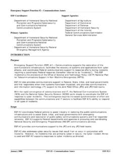
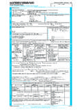
4 The shipping ramp (5,200 square feet in area, approximately 10 percent of the WTC 7 site) was used by the entire WTC complex. Table WTC 7 Tenants Floor TeTenant 46-47 Mechanical Floors 28-45 Salomon Smith Barney (SSB) 26-27 Standard Chartered Bank 25 Internal Revenue Service (IRS) Department of Defense (DOD) Central Intelligence Agency (CIA) 24 Internal Revenue Service (IRS) 23 Office of Emergency Management (OEM) 22 Federal Home Loan Bank of New York 21 First State Management Group 19-21 ITT Hartford Insurance Group 19 National Association of Insurance Commissioners (NAIC) Securities Valuation Office 18 Equal Employment Opportunity Commission (EEOC) 14-17 Vacant 13 Provident Financial Management 11-13 Securities and Exchange Commission 9-10 Secret Service 7-8 American Express Bank International 7 part OEM generators and day tank 6 Switchgear, storage 5 Switchgear, generators, transformers 4 Upper level of 3rd floor lobby, switchgear 3 Lobby, SSB Conference Center, rentable space, management offices 2 Open to 1st floor lobby, transformer vault upper level, upper level switchgear 1 Lobby, loading docks, existing Con Ed transformer vaults, fuel storage, lower level switchgear 5-2 WORLD TRADE CENTER BUILDING PERFORMANCE STUDY Chapter 5: WTC 7 246' - 7 " New Column New Caisson Existing Column Existing Caisson 77' - 9 "66' - 8 " 37' - 1" 52' - 1" 55' - 3" 42' - 0" 329' - 0 " Ramp Con Ed Substation Face of WTC 7 Above WTC 7 Original Footprint Core Figure 5-1 Foundation plan WTC 7.
5 Structural Description Foundations With the development of an office tower in mind, the Port Authority of New York and New Jersey (hereafter referred to as the Port Authority) installed caissons intended for future construction. However, Seven World Trade Company, Silverstein Development Corporation, General Partner, decided to construct a building much larger in both height and floor area. The designers combined the existing caissons inside the substation with new caissons inside and outside the substation to create the foundation for WTC 7. Figure 5-1 shows the location of pre-existing caissons built when the Con Ed substation was constructed along with new caissons that were installed for the support of the building. The discrepancy in the column locations between the substation and the office tower required transfers to carry loads from the office tower to the substation and finally into the foundation.
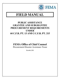
6 Old and new caissons, as well as old and new columns, also can be seen in the foundation plan shown in Figure 5-1. Structural Framing The typical floor framing shown in Figure 5-2 was used for the 8th through the 45th floors. The gravity framing consisted of composite beams (typically W16x26 and W24x55) that spanned from the core to the perimeter. The floor slab was an electrified composite 3-inch metal deck with 2-1/2-inch normal-weight concrete fill spanning between the steel beams. Below the 8th floor, floors generally consisted of formed slabs Federal Emergency MANAGEMENT AGENCY 5-3 Chapter 5: WTC 7 with some limited areas of concrete-filled metal decks. There were numerous gravity column transfers, the more significant of these being three interior gravity column transfers between floors 5 to 7 and eight cantilever column transfers in the north elevation at the 7th floor. The column transfers in the exterior walls are shown in the bracing elevations (Figure 5-3).
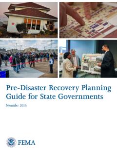
7 The lateral load resisting system consisted of four perimeter moment frames, one at each exterior wall, augmented by two-story belt trusses between the 5th and 7th floors and between the 22nd and 24th floors. There were additional trusses at the east and west elevations below the 7th floor. An interior braced core extended from the foundation to the 7th floor. The horizontal shear was transferred into the core at the 5th and the 7th floors. The 5th floor diaphragm (plan shown in Figure 5-4) consisted of a reinforced concrete 14-inch-thick slab with embedded steel T-sections. The 7th floor was an 8-inch-thick reinforced concrete slab. The 5th and 7th floors contained the diaphragm floors, belt trusses, and transfer girders. A 3-D rendering of Truss 1, Truss 2, Truss 3, and several cantilever transfer girders is shown in Figure 5-5. Transfer Trusses and Girders The transfer trusses and girders, shown in Figure 5-6, were located between the 5th and 7th floors.
8 The function and design of each transfer system are described below. Tr uss 1 was situated in the northeast sector of the core, and spanned in the east-west direction. As shown in Figure 5-7, this truss was a two-story double transfer structure that provided load transfers between nonconcentric columns above the 7th floor to an existing column and girder at the 5th floor. The girder then provided a second load transfer to an additional two columns. The 7th floor column supported 41 floors and part of the east mechanical penthouse. Its load was transferred through the triangular truss into a column located above an existing substation column and girder at the 5th floor. The built-up double web girder spanned in the north-south direction between two new columns that started at the foundation and terminated at the 7th floor. The truss diagonals were W14 shapes and the horizontal tie was a 22-ton, built-up shape.
9 Low-Rise Elevators High-Rise Elevators Service Elevators Stairwells Figure 5-2 Plan view of typical floor framing for the 8th through 45th floors. 5-4 WORLD TRADE CENTER BUILDING PERFORMANCE STUDY Chapter 5: WTC 7 Figure 5-3 Elevations of building and core area. Federal Emergency MANAGEMENT AGENCY 5-5 Chapter 5: WTC 7 Low-Rise Elevators High-Rise Elevators Service Elevators Figure 5-4 Fifth floor diaphragm plan showing T-sections embedded in 14-inch slab. Tr uss 3 (Figure 5-9) Core Floor 7 Floor 6 Floor 6 Floor 6 Floor 5 Floor 4 Tr uss 1 (Figure 5-7) Cantilever Tr ansfer Girders (Figure 5-10) Tr uss 2 (Figure 5-8) Note: Some structural members omitted for clarity. Figure 5-5 3-D diagram showing relation of trusses and transfer girders. 5-6 WORLD TRADE CENTER BUILDING PERFORMANCE STUDY Chapter 5: WTC 7 Figure 5-6 Seventh floor plan showing locations of transfer trusses and girders.
10 Tr uss 2 was a single transfer located south of Truss 1. As shown in Figure 5-8, Truss 2 transferred the column load from the 7th floor through a triangular truss into two existing columns at the 5th floor. Large gusset plates were provided at the connection between the diagonals, the columns, and the horizontal tie. The diagonals and the built-up horizontal tie were field-welded. Tr uss 3 was a cantilevered two-story transfer structure in the north-south direction between the 5th and 7th floors at the western end of the core area. As shown in Figure 5-9, Truss 3 transferred the loads between columns. The upper columns carried 41 floors of load and were cantilevered to the north of the column that went from the foundation to the 7th floor. The cantilever transfer girders, shown in Figure 5-10, spanned between the core and the north elevation at the 7th floor. There were eight transfer girders to redirect the load of the building above the 7th floor into the columns that went through the Con Ed substation.