Transcription of FFT based target detection using FMCW Radar - IOSR Journals
1 IOSR journal of VLSI and Signal Processing (IOSR-JVSP) Volume 6, Issue 4, Ver. II (Jul. - Aug. 2016), PP 13-18 e-ISSN: 2319 4200, p-ISSN No. : 2319 4197 DOI: 13 | Page FFT based target detection using FMCW Radar Rajesha K V1, Dr. U B Mahadevaswamy2 1 Mtech in Industrial Electronics, SJCE, Mysuru, INDIA 2 Associate Professor, Department of electronics, SJCE, Mysuru, INDIA Abstract: RAdio detection And Ranging ( Radar ) has been used since 1930 s for the detection and estimation of target related information. Earlier Pulse radars were used to determine the target , in which there was time interval between the transmissions of pulses, which in turn induced error in determination of target . To prevent this ambiguity Continuous Wave (CW) radars were used, non modulated CW Radar was unable to find velocity of target .
2 So Frequency Modulated Continuous Wave (FMCW) Radar is used when we have to find velocity of moving target . The purpose of this work is to develop a 1024 point FFT code for FMCW Radar , through which we can convert any physical signal to frequency domain, and we are extending the same to find velocity of the target with higher precision and faster rate and also to simulate the same using FPGA. Keywords: Radar , FMCW, FFT, FPGA, target , Range, Velocity I. Introduction Radar is a target detection system that uses radio waves to detect target and its related information like range, angle, velocity, direction. It can be used to detect targets like flights, spacecrafts, submarines, missiles, vehicles. It is also used to find weather related information [1]. Radar transmits electromagnetic waves which are bounced back from the target in the path.
3 The reflected waves are called echoes, which contains target related information. Electromagnetic waves travels through air at a constant speed, at approximately the speed of light, 300,000 kilometers per second. In time domain we can only know the value of the signal at a particular time, it will not provide information about the rate at which the signal is varying, and hence we have to transmit the signal in frequency domain. Fourier Transforms helps us to change a time domain signal to frequency domain [3]. In this work we are using Fast Fourier Transform for signal processing which will increase the speed of the system [4]. In Pulse radars, a series of short duration pulses are sent. A time gap is elapsed between transmissions of each pulse. Time gap is randomly calculated based on the maximum expected range of the target [6].
4 Pulse duration will be in micro second, whereas the time gap is in millisecond. The increased time gap leads to miss some target detection and also to increase False Alarm Ratio (FAR), which is a serious drawback of pulse radars. Continuous wave (CW) radars were used to overcome the drawback of pulse radars. Now the challenge is to locate and find the velocity of moving targets like aircraft, missiles, etc. FMCW Radar plays an important role in finding and estimating data related to moving targets [1]. FMCW Radar transmits a frequency modulated continuous wave, the echo signal is time delayed and Doppler shifted version of the transmitted wave. The time delay is used to find the range of the target and Doppler shift is used to find the velocity of the target .
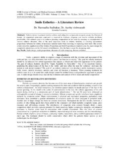
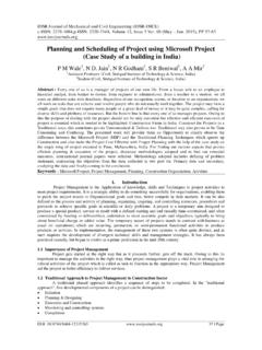
5 The signal to noise ratio is highly improved in FMCW Radar compared to pulse radars, and false alarm rate is reduced in FMCW Radar . Figure 1: Time vs. Frequency plot of transmitted and received signal in FMCW Radar . FFT based target detection using FMCW Radar DOI: 14 | Page The target related information like Range can be estimated using Equation 1 and velocity can be found by using Equation 2 by obtaining the required parameters from the received Radar signal. = = (1) Where: C = speed of light = 3 * 108 m/s t = propagation delay [s] f = frequency difference [Hz] df/dt = frequency shift per unit of time In the proposed work as we are not working on real time Radar , the time taken by the transmitted signal to return to the Radar is unknown; hence we are not finding the range of the target .
6 = (2) Where: ft = transmitted signal frequency To find velocity of the target it is not possible without converting signal in frequency domain, in this work we develop a VHDL code for 1024 point FFT using IP cores of Quartus II, so that we can readily use it in DSP chips. And we assume that the received signal is 10 percent frequency shifted transmitted signal and the velocity of the target was found. II. Implementation Here we are going to discuss about the design flow of software implementation and block diagram of hardware implementation 1. Software implementation We have used both MATLAB and Quartus II altera in our work, MATLAB is used for simulation purpose, but Quartus II software easily adapts to the specific design needs.
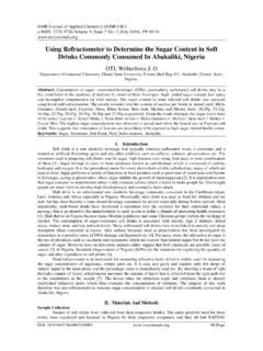
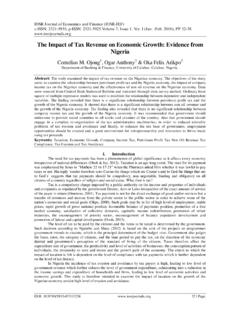
7 It includes solutions for all phases of FPGA and CPLD design. We use mega functions and IP functions of Quartus II to instantiate our design [13]. Figure 2 shows design flow of developing 1024 point FFT code using MATLAB and Quartus II, the design flow is done in a preset hierarchy and is clearly explained in the flowchart. The 1024 point FFT code was first realized in MATLAB without using the inbuilt FFT function, but MATLAB is not a hardware descriptive language, hence further the same code was realized in hardware description language in Quartus II altera, so that it can be used on FPGA. FFT based target detection using FMCW Radar DOI: 15 | Page Figure 2: Design flow of developing 1024 point FFT code using MATLAB and Quartus II.
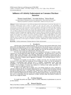
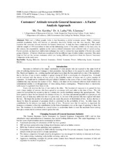
8 2. Hardware implementation The block diagram of proposed methodology is shown in the Figure 3; it consists of two major blocks A. Host machine B. FPGA Host machine is the one through which we can build our design with the help of software, it may be PC, laptop, tablet, which is compatible for the usage of software. The output is examined with the help of host machine. Figure 3: Block diagram of implementation FFT based target detection using FMCW Radar DOI: 16 | Page The FPGA used in this proposed work is EP3C120F780I7 (Cyclone III device family by altera), it s a package of 780 pins and having a speed grade 7 [12]. Its operating temperature range varies from -40 to100 degree Celsius. It is operated with 5 Volts, 2 Ampere regulated power supply.
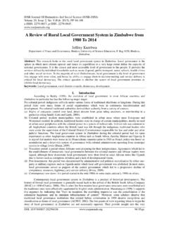
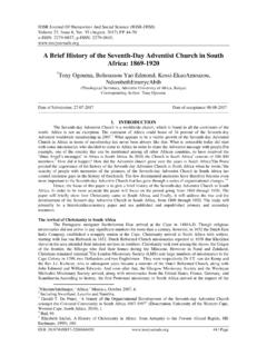
9 USB blaster is used to interface host machine with FPGA, the program is loaded to FPGA with the help of USB blaster. And regulated power supply provides the required voltage and current for FPGA III. Results We have tapped all the required input and output signals provided to FPGA in Signal Tap II Logic Analyzer of Quartus II altera. The main output signals like Doppler shift, received frequency, velocity can be observed in figure 4 and figure result shown is for received signal which is 10 percent frequency shifted transmitted signal, processed with 1024 point FFT. If the received signal frequency is more than transmitted signal frequency, then the target is travelling towards the Radar . If the received signal frequency is less than the transmitted signal frequency, then the target is moving away from the Radar .
10 In Figure 4, transmitted signal frequency is 100 Hz, but in Figure 5, transmitted signal frequency is 1000 Hz. Figure 4. Signal Tap II Logic Analyzer output for 100Hz transmitted freq and 110 Hz received frequency FFT based target detection using FMCW Radar DOI: 17 | Page Figure 5. Signal Tap II Logic Analyzer output for 1000 Hz transmitted and 1100 Hz received frequency The velocity in both figure 4 and figure 5 should be same, as Doppler shift is 10 percent. The calculated velocity is 15000000, but we can observe that there is error in detection of velocity in Figure 5, that is because variation in delta. = (3) Where: ft = transmitted signal frequency N = number of FFT points.