Transcription of FIBER OPTIC CONNECTOR SPLICING MODULE
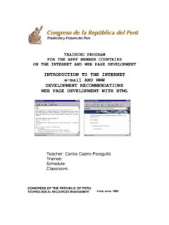
1 FIBER OPTIC CONNECTOR &. SPLICING MODULE . Supplemental Curriculum for the FIBER OPTIC Demonstration System INDUSTRIAL FIBER O PTICS. *. Copyright 2009. Previous Printing 2001. by Industrial FIBER Optics, Inc. IF 120231 Teacher's Manual Revision A. Printed in the United States of America * * *. All rights reserved. No part of this publication may be reproduced, stored in a retrieval system, or transmitted in any form or by any means (electronic, mechanical, photocopying, recording, or otherwise). without prior written permission from Industrial FIBER Optics, Inc. * * * * *. INDUSTRIAL FIBER OPTICS, INC. 1725 West 1 st Street Tempe, AZ 85281-7622 USA. BEFORE YOU BEGIN .. The Industrial FIBER Optics' FIBER OPTIC CONNECTOR and SPLICING MODULE contains three learning activities that cover the basics of attaching connectors and splices to FIBER OPTIC cables.
2 These technical and highly sought-after skills in the FIBER optics industry are taught using a hands-on approach. Each activity will take roughly 50 minutes to complete. This MODULE is suitable for science, physics, industrial technology and vocational education classes at grades 11 and above. This MODULE is a complete curriculum package no additional materials are required except to complete some homework assignments using a library or the Internet. The FIBER OPTIC CONNECTOR and SPLICING MODULE was designed to be used as a supplement for the Industrial FIBER Optics FIBER OPTIC Demonstration System, although it can be used separately. The FIBER OPTIC Demonstration System has been sold in glass and plastic versions by Industrial FIBER Optics (IF-DS100G & IF-DS100P) and in a plastic version by Scientific Laser Connection. This product is compatible with all versions of the FIBER OPTIC Demonstration System.
3 This manual will guide instructors and students through the three separate activities. Each activity has assignments containing reading assignments, lab exercises which involve working with FIBER optics, worksheets containing questions and homework assignments. Industrial FIBER Optics makes every effort to incorporate state-of-the-art technology, highest quality and dependability in its products. We constantly explore new ideas and products to best serve the rapidly expanding needs of industry and education. We encourage comments that you may have about our products, and we welcome the opportunity to discuss new ideas that may better serve your needs. For more information about our company or any new products that we have to offer, refer to our web site listed below on the Worldwide Web at: Thank you for selecting this Industrial FIBER Optics product.
4 We hope it meets your expectations and provides many hours of productive activity. -i- - ii - Table of Contents Before You i Activity 1: 1. Lab Exercise #1 - EQUIPMENT FAMILIARIZATION .. 2. Worksheet #1 .. 5. Activity 2: INSTALLING A FIBER 7. Reading Assignment #2 - FIBER O PTIC C ONNECTORS .. 9. Lab Exercise #2 - INSTALLATION .. 14. Worksheet #2 .. 20. Activity 3: FIBER CABLE 21. Reading Assignment #3 - SPLICES .. 22. Lab Exercise #3 - SPLICING A FIBER C 25. Worksheet #3 .. 27. TEACHER 'S M ANUAL ONLY. To the Instructor.. 29. Replacement Parts List.. 30. Worksheet Answers.. 31. - iii - - iv - ACTIVITY 1. Section Guide INVENTORY. ACTIVITY 2. INSTALLING A FIBER . CONNECTOR . ACTIVITY 3. FIBER CABLE SPLICING . INVENTORY. ACTIVITY #1: This activity is intended to acquaint you with Industrial FIBER Optics' FIBER OPTIC CONNECTOR and Splice modular training curriculum.
5 You will set up equipment, identify each item that you will be using in the next two activities and familiarize yourself with a specialized microscope. Equipment Needed: ! All the components that are part of this MODULE . Please refer to the parts list on page 4. To complete this activity you must: 1. Complete Lab Exercise #1 - Equipment Familiarization on page 2 and take inventory of all the equipment in this MODULE . If you are missing any equipment or parts, let your instructor know before continuing. You may refer to the parts list on page 4 to help describe the components. 2. Answer all Questions on Worksheet #1. 3. Complete Homework Assignment #1. Homework Assignment #1: At a library or on the Internet, find a company that sells or manufactures tool kits for putting connectors or splices on FIBER cables. Compare the items in these tool kits to those contained in this MODULE and describe the similarities.
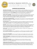
6 Photo 1. Installed FIBER OPTIC cables appear similar to copper cabling, but carry much more communications bandwidth. -1- EQUIPMENT FAMILIARIZATION. Lab Exercise #1. In the first Lab Exercise students identify and inventory all items furnished with this FIBER OPTIC training MODULE . This inventory process is required since it will introduce you to the technical terms used in this manual and speed completion of the following two activities. Procedure 1. Choose a flat, level table approximately 90 ! 120 cm (3 ! 4 feet) in size as your work area for this exercise. 2. At your work area, assemble all materials your instructor provides for you. 3. Locate the only item with an electrical cord attached. This is a 25-watt heating element that is part of the Hot Knife assembly you will use to cut plastic FIBER . 4. Determine if the heating element has a knife tip attached.
7 If not, locate a clear plastic bottle that contains a knurled brass collar and a threaded chuck about mm (.3 inches) in diameter and 32 mm ( inches)long. Remove the collar, chuck and Exacto knife blade from the enclosure. 5. Slide the threaded end of the slotted brass chuck through the large opening of the knurled cinch nut. Push the chuck through the cinch nut until the thread comes out the small opening in the cinch nut. 6. Thread the brass chuck/cinch nut assembly into the threaded end of the heating element until it lightly touches bottom. Use your fingers to turn the slotted end of the brass chuck for this purpose. Do not tighten any further at this time 7. Insert the square (non-cutting) end of the Exacto knife blade into the slot in the chuck. Make certain the square end of the blade slides past the large opening in the knurled cinch nut.
8 CAUTION: DO NOT TOUCH OR PRESS THE CUTTING END. OF THE BLADE WITH YOUR FINGERS OR INJURY MAY RESULT. GRASP THE. BLADE ONLY ON THE FLAT PORTIONS. 8. Tighten the cinch nut so that the chuck firmly clamps the Exacto knife. Finger tighten only you must allow some room for thermal expansion when the heating element is powered. 9. Identify the remaining components in Table 1. Write in the column marked ACTIVITY 1 the number of components you found. If the number that you identify does not match the numbers in Column 2, notify your instructor. 10. Reference the parts list in Table 3 for part numbers for each of these items, for future reordering. -2- 11. The inspection microscope that you identified above is a specially designed tool for examining the ends of optical fibers. Please read the following paragraph and familiarize yourself with microscope operation to save steps in the next activities.
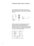
9 FIBER inspection microscope - A specialized tool for viewing the tip or termination of FIBER OPTIC connectors . One end of the microscope has a clear plastic hood with an adapter into which an ST FIBER CONNECTOR tip is inserted. A swiveling light bulb illuminates the FIBER end. The other end of the microscope contains the eyepiece through which the FIBER is viewed. On one narrow side of the microscope there may be a sliding adjustment (ZOOM) that moves the eyepiece. This varies the magnification of the microscope. On the opposite side there is a slide switch that turns the light bulb on and off. There is a focus wheel in the center of the microscope with an exposed edge on two sides. Turning this wheel will adjust the focus of the microscope. A small sliding adjustment on one face of the microscope (near the end with the clear plastic hood) sets the angle of the light bulb.
10 The ST adapter has a slot that allows light from the bulb to shine on the FIBER end. Changing the position of this slot will adjust the amount of light that falls on the FIBER termination. These two adjustments can be used to vary the lighting conditions under which the termination is viewed. 12. Locate an ST style CONNECTOR from the parts kit. The CONNECTOR body has a knurled locking ring with bayonet style slots. This is attached to a metal cylinder which has a large diameter hole on one end and a small one on the other. The cylinder end with the small hole is the FIBER ferrule. 13. Insert the ferrule tip into the adapter on the microscope until the ferrule body is completely seated. Turn on the microscope light and as required adjust the angle of the light bulb so the ferrule tip is illuminated. 14. While looking through the eyepiece adjust the focus wheel until the ferrule tip comes into focus.