Transcription of Photoelectric Sensors Theory of Operation - …
1 80 Photoelectric Sensors Theory of OperationA Photoelectric sensor is another type of position sensingdevice. Photoelectric Sensors , similar to the ones shown below,use a modulated light beam that is either broken or reflected bythe control consists of an emitter (light source), a receiver todetect the emitted light, and associated electronics thatevaluate and amplify the detected signal causing thephotoelectric s output switch to change state. We are all familiarwith the simple application of a Photoelectric sensor placed inthe entrance of a store to alert the presence of a customer. This,of course, is only one possible LightModulated light increases the sensing range while reducing theeffect of ambient light.
2 Modulated light is pulsed at a specificfrequency between 5 and 30 KHz. The Photoelectric sensor isable to distinguish the modulated light from ambient light. Lightsources used by these Sensors range in the light spectrum fromvisible green to invisible infrared. Light-emitting diode (LED)sources are typically is possible that two Photoelectric devices operating in closeproximity to each other can cause interference. The problemmay be rectified with alignment or covers. The followingclearances between Sensors are given as a starting point. Insome cases it may be necessary to increase the distancebetween ModelDistanceD4 mm / M550 mmM12250 mmM18250 mmK31250 mmK30500 mmK40750 mmK80500 mmL18150 mmL50 (Diffuse)30 mmL50 (Thru-Beam) 80 mm82 Excess GainMany environments, particularly industrial applications, includedust, dirt, smoke, moisture, or other airborne contaminants.
3 Asensor operating in an environment that contains thesecontaminants requires more light to operate properly. There aresix grades of Air (Ideal condition, climate controlled or sterile) Contamination (Indoor, nonindustrial areas, officebuildings) Contamination (Warehouse, light industry, materialhandling operations ) Contamination (Milling operations , highhumidity, steam) Contamination (Heavy particle laden air, extremewash down environments, grain elevators) Contamination (Coal bins, residue on lens)Excess gain represents the amount of light emitted by thetransmitter in excess of the amount required to operate thereceiver.
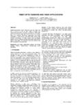
4 In clean environments an excess gain equal to orgreater than 1 is usually sufficient to operate the sensor sreceiver. If, for example, an environment contained enoughairborne contaminants to absorb 50% of the light emitted bythe transmitter, a minimum excess gain of 2 would be requiredto operate the sensor s gain is plotted on a logarithmic chart. The exampleshown below is an excess gain chart for an M12 thru-beamsensor. If the required sensing distance is 1 m there is anexcess gain of 30. This means there is 30 times more light thanrequired in clean air hitting the receiver. Excess gain decreasesas sensing distance increases.
5 Keep in mind that the sensingdistance for thru-beam Sensors is from the transmitter to thereceiver and the sensing distance for reflective Sensors is fromthe transmitter to the ZonesPhotoelectric Sensors have a switching zone. The switchingzone is based on the beam pattern and diameter of the lightfrom the sensor s emitter. The receiver will operate when atarget enters this symbols are used in the sensor catalog (SFPC-08000)to help identify the type of Photoelectric sensor . Some symbolsare used to indicate a sensor s scan technique, such as diffuse,retroreflective, or thru beam. Other symbols identify a specificfeature of the sensor , such as fiber-optics, slot, or color TechniquesA scan technique is a method used by Photoelectric Sensors todetect an object (target).
6 In part, the best technique to usedepends on the target. Some targets are opaque and others arehighly reflective. In some cases it is necessary to detect achange in color. Scanning distance is also a factor in selecting ascan technique. Some techniques work well at greaterdistances while others work better when the target is closer tothe emitter and receiver units are required for a thru-beamsensor. The units are aligned in a way that the greatest possibleamount of pulsed light from the transmitter reaches thereceiver. An object (target) placed in the path of the light beamblocks the light to the receiver, causing the receiver s output tochange state.
7 When the target no longer blocks the light paththe receiver s output returns to its normal is suitable for detection of opaque or reflectiveobjects. It cannot be used to detect transparent objects. Inaddition, vibration can cause alignment problems. The highexcess gain of thru-beam Sensors make them suitable forenvironments with airborne contaminants. The maximumsensing range is 300 Effective BeamThe effective beam of a Photoelectric sensor is the region ofthe beam s diameter where a target is detected. The effectivebeam on a thru-beam sensor is the diameter of the emitter andreceiver lens. The effective beam extends from the emitter lensto the receiver lens.
8 The minimum size of the target shouldequal the diameter of the orReflective and retroreflective scan are two names for the sameRetroreflective Scantechnique. The emitter and receiver are in one unit. Light fromthe emitter is transmitted in a straight line to a reflector andreturns to the receiver. A normal or a corner-cube reflector canbe used. When a target blocks the light path the output of thesensor changes state. When the target no longer blocks thelight path the sensor returns to its normal state. The maximumsensing range is 35 ScanThe effective beam is tapered from the sensor s lens to theEffective Beamedges of the reflector.
9 The minimum size of the target shouldequal the size of the are ordered separately from Sensors . Reflectorscome in various sizes and can be round or rectangular in shapeor reflective tape. The sensing distance is specified with aparticular reflector. Reflective tape should not be used withpolarized retroreflective ScanRetroreflective scan Sensors may not be able to detect shinyand Shiny Objectsobjects. Shiny objects reflect light back to the sensor . Thesensor is unable to differentiate between light reflected from ashiny object and light reflected from a variation of retroreflective scan is polarized retroreflectiveRetroreflective Scanscan.
10 Polarizing filters are placed in front of the emitter andreceiver lenses. The polarizing filter projects the emitter s beamin one plane only. This light is said to be polarized. A corner-cubereflector must be used to rotate the light reflected back to thereceiver. The polarizing filter on the receiver allows rotated lightto pass through to the receiver. In comparison to retroreflectivescan, polarized retroreflective scan works well when trying todetect shiny ScanThe emitter and receiver are in one unit. Light from the emitterstrikes the target and the reflected light is diffused from thesurface at all angles. If the receiver receives enough reflectedlight the output will switch states.