Transcription of FIBER OPTICS
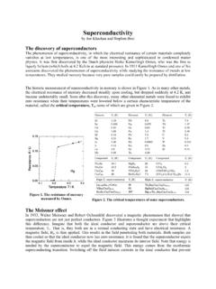
1 CHAPTER 8 FIBER OPTICS STEP-INDEX FIBERS A. Guided Rays B. Guided Waves C. single -Mode Fibers GRADED-INDEX FIBERS A. Guided Waves B. Propagation Constants and Velocities ATTENUATION AND DISPERSION A. Attenuation B. Dispersion C. Pulse Propagation Dramatic improvements in the development of low-loss materials for optical fibers are responsible for the commercial viability of FIBER -optic communications. Corning Incorpo- rated pioneered the development and manu- facture of ultra-low-loss glass fibers. C 0 R N I N G 272 Fundamentals of PhotonicsBahaa E. A. Saleh, Malvin Carl TeichCopyright 1991 John Wiley & Sons, : 0-471-83965-5 (Hardback); 0-471-2-1374-8 (Electronic)An optical FIBER is a cylindrical dielectric waveguide made of low-loss materials such as silica glass.
2 It has a central core in which the light is guided, embedded in an outer cladding of slightly lower refractive index (Fig. ). Light rays incident on the core-cladding boundary at angles greater than the critical angle undergo total internal reflection and are guided through the core without refraction. Rays of greater inclina- tion to the FIBER axis lose part of their power into the cladding at each reflection and are not guided. As a result of recent technological advances in fabrication, light can be guided through 1 km of glass FIBER with a loss as low as = dB (= %). Optical fibers are replacing copper coaxial cables as the preferred transmission medium for electro- magnetic waves, thereby revolutionizing terrestrial communications.
3 Applications range from long-distance telephone and data communications to computer communications in a local area network. In this chapter we introduce the principles of light transmission in optical fibers. These principles are essentially the same as those that apply in planar dielectric waveguides (Chap. 71, except for the cylindrical geometry. In both types of waveguide light propagates in the form of modes. Each mode travels along the axis of the waveguide with a distinct propagation constant and group velocity, maintaining its transverse spatial distribution and its polarization. In planar waveguides, we found that each mode was the sum of the multiple reflections of a TEM wave bouncing within the slab in the direction of an optical ray at a certain bounce angle.)
4 This approach is approximately applicable to cylindrical waveguides as well. When the core diameter is small, only a single mode is permitted and the FIBER is said to be a single -mode FIBER . Fibers with large core diameters are multimode fibers. One of the difficulties associated with light propagation in multimode fibers arises from the differences among the group velocities of the modes. This results in a variety of travel times so that light pulses are broadened as they travel through the FIBER . This effect, called modal dispersion, limits the speed at which adjacent pulses can be sent without overlapping and therefore the speed at which a FIBER -optic communication system can operate.
5 Modal dispersion can be reduced by grading the refractive index of the FIBER core from a maximum value at its center to a minimum value at the core-cladding boundary. The FIBER is then called a graded-index FIBER , whereas conventional fibers Figure An optical FIBER is a cylindrical dielectric waveguide. 273 274 FIBER OPTICS W -- (cl -- n1 I n2 --- a-- r n1 me-_ -A- -- n2 --- l} nl --- -- Figure Geometry, refractive-index profile, and typical rays in: (a) a multimode step-index FIBER , (b) a single -mode step-index FIBER , and (c) a multimode graded-index FIBER . with constant refractive indices in the core and the cladding are called step-index fibers.)
6 In a graded-index FIBER the velocity increases with distance from the core axis (since the refractive index decreases). Although rays of greater inclination to the FIBER axis must travel farther, they travel faster, so that the travel times of the different rays are equalized. Optical fibers are therefore classified as step-index or graded-index, and multimode or single -mode, as illustrated in Fig. This chapter emphasizes the nature of optical modes and their group velocities in step-index and graded-index fibers. These topics are presented in Sets. and , respectively. The optical properties of the FIBER material (which is usually fused silica), including its attenuation and the effects of material, modal, and waveguide dispersion on the transmission of light pulses, are discussed in Sec.
7 Optical fibers are revisited in Chap. 22, which is devoted to their use in lightwave communication systems. STEP-INDEX FIBERS A step-index FIBER is a cylindrical dielectric waveguide specified by its core and cladding refractive indices, ~zr and n2, and the radii a and b (see Fig. ). Examples of standard core and cladding diameters 2a/2b are S/125, 50/125, , 85/125, 100/140 (units of pm). The refractive indices differ only slightly, so that the fractional refractive-index change A = l - n2 ( ) nl is small (A < 1). Almost all fibers currently used in optical communication systems are made of fused silica glass (SiO,) of high chemical purity.
8 Slight changes in the refractive index are STEP-INDEX FIBERS 275 made by the addition of low concentrations of doping materials (titanium, germanium, or boron, for example). The refractive index y1r is in the range from to , depending on the wavelength, and A typically lies between and A. Guided Rays An optical ray is guided by total internal reflections within the FIBER core if its angle of incidence on the core-cladding boundary is greater than the critical angle 8, = sin - (n,/nt ), and remains so as the ray bounces. Meridional Rays The guiding condition is simple to see for meridional rays (rays in planes passing through the FIBER axis), as illustrated in Fig.
9 These rays intersect the FIBER axis and reflect in the same plane without changing their angle of incidence, as if they were in a planar waveguide. Meridional rays are guided if their angle 8 with the FIBER axis is smaller than the complement of the critical angle GC = VT/~ - 8, = cos-l&/n,). Since rrr = n2, 8, is usually small and the guided rays are approximately paraxial. Meridional plane Figure The trajectory of a meridional ray lies in a plane passing through the FIBER axis. The ray is guided if 8 < aC = cos- (n,/n,). Skewed Rays An arbitrary ray is identified by its plane of incidence, a plane parallel to the FIBER axis and passing through the ray, and by the angle with that axis, as illustrated in Fig.
10 The plane of incidence intersects the core-cladding cylindrical boundary at an angle C#I with the normal to the boundary and lies at a distance R from the FIBER axis. The ray is identified by its angle 8 with the FIBER axis and by the angle 4 of its plane. When 4 # 0 (R f 0) the ray is said to be skewed. For meridional rays C$ = 0 and R = 0. A skewed ray reflects repeatedly into planes that make the same angle 4 with the core-cladding boundary, and follows a helical trajectory confined within a cylindrical shell of radii R and a, as illustrated in Fig. The projection of the trajectory onto the transverse (x-y) plane is a regular polygon, not necessarily closed.