Transcription of Field Testing of Medium- - netaworld.org
1 Fall 2006 NETA WORLD FeatureField Testing of Medium- and High-Voltage Cablesby Vern Buchholz, about ten years ago, Testing the insulation on medium- and high-voltage power cable was straightforward. DC high potential tests were the industry norm. DC high potential Testing was developed in the days of oil-paper insulation, and because of the simple and easy-to-use equipment, continued to be used when extruded cables arrived. However, as extruded cables became widespread, it was noticed that although some cable systems passed the dc high potential test, they failed shortly after being put in service. Suspicions arose, particularly with aged polyethylene insulation, that the dc high potential test was somehow damaging the insulation. These suspicions were confirmed by an EPRI study published in the early 1990 Testing agencies and utilities stopped performing routine dc high po-tential tests on aged extruded cables.
2 NETA, in its Testing specifications, reflects the concern by limiting the dc overpotential maximum test voltage for cables less than five years after installation and by not recommending dc high potential Testing for those over five years in service. In response to the changes in cable test requirements and increasing age of the cable systems in North America and Europe, manufacturers and service organizations are developing many new forms of cable Testing . So many tech-niques have come on the market, that electrical testers are overwhelmed and often confused. In this article, I will discuss the cable Field - Testing standards developed or under development by the IEEE Insulated Conductors Committee. I will summarize where I see cable Field Testing is now and were it is heading. IEEE Insulated Conductors Committee and Cable Field TestingThe Insulated Conductors Committee (ICC) under the Power Engineering Society (PES) of the IEEE meets twice yearly and provides one of the best forums in North America for the development of power cable standards.
3 Those seeking more information and copies of the meeting minutes can refer to the ICC website ( ). Subcommittee C, Cable Systems, of the ICC has five Working Groups (WGs) specifically covering vari-ous aspects of cable Field Testing . WG C-15 has completed ballot-ing and the IEEE Standards As-sociation issued IEEE 400, IEEE Guide for Field Testing and Evalu-ation of the Insulation of Shielded Power Cable Systems. This guide is an omnibus document cover-ing cable insulation Field Testing in general. The overview of this guide defines two types of Field tests: Type 1 Field tests, or withstand tests, are intended to detect defective parts and allow for replacement or repair. These tests are usually achieved by applica-tion of a moderately increased voltage across the insulation for a prescribed duration.
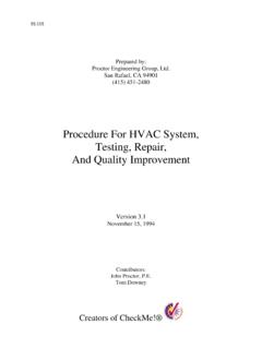
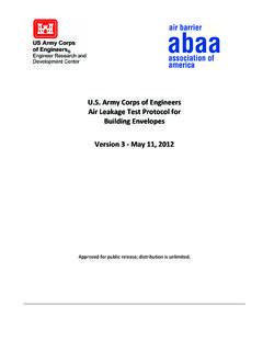
4 These are pass/fail tests performed after installation or repair. Type 2 Field tests, also called diagnostic tests or condition as-sessments, determine the health of cable system insulation or lo-cate discrete defects that may be-come failures in the future. These tests are usually performed by means of moderately increased voltages applied for relatively short duration or by means of low voltages. W hile Type 2 insulation tests are conducted, other parts of the system such as jackets, shields, and connectors may also be diagnosed. NETA WORLD Fall 2006 Figure 1 Corroded taped shield leading to failureIEEE 400 provides a summary of the various insulation test methods, gives the advantages and disadvantages of each, and sets the stage for a series of more detailed guides covering each insulation test method.
5 At this time three additional working groups of the ICC are meeting and covering dc, very low frequency (VLF), and partial discharge (PD) Testing in detail. DC Cable Field Testing WG C-17 is writing IEEE , Draft IEEE Guide for Field - Testing of Laminated Dielectric, Shielded Power Cable Systems Rated 5 kV and Above with High Direct Current Voltage. This guide is presently in the voting process and is expected to be issued in the fall. The guide will only cover dc high potential Testing on laminated (oil-paper insulated) cable, not on extruded cable, because of the concerns mentioned at the beginning of this article. The guide gives voltage levels and durations for withstand tests. It also gives methods for calculating insulation resistance and interpreting these values as a diagnostic tool.
6 There is still interest at the ICC in using lower voltage, short duration dc tests to perform Type 2 or diagnostic test-ing on cables with extruded insulation. These tests include leakage or polarization current measurement, isothermal relaxation current (IRC), and the voltage recovery method (VRM). These dc diagnostic tests will be addressed in future meetings of WG C-17. Very Low Frequency Cable Field TestingWG C-18 has completed the balloting process on IEEE IEEE Guide for Field Testing of Shielded Power Cable Systems Using Very Low Frequency (VLF) , and the IEEE issued the guide in 2004. IEEE discusses in detail all commonly available VLF waveforms (1 Hz and less), including: Cosine-rectangular/bipolar pulse waveform Sinusoidal waveform Bipolar rectangular waveform Alternating regulated positive and negative dc step voltagesAs covered in this guide, VLF can be used in both Type 1 or Type 2.
7 VLF test voltage withstand levels are provided in tables in the guide for installation, acceptance, and mainte-nance withstand tests. The recommended Testing time varies between 15 to 60 are a number of diagnostic tools that are used with VLF Testing as detailed in IEEE The methods as used with each waveform along with the advantages and disadvantages are given. The diagnostic methods for VLF include: Dissipation-factor (tan delta) measurement Differential dissipation-factor measurement Dielectric spectroscopy Loss current harmonics Leakage current PD measurement When this guide was published research was still con-tinuing on the VLF withstand levels and durations and on the interpretation of the various diagnostic methods. The conclusions of the guide state, VLF Testing techniques, along with other test techniques, are continuing to improve and develop.
8 Meaningful interpretation of the test results will require development of a database to better define ac-ceptance criteria. With this in mind, the WG C-18 con-tinues to meet at the ICC meetings with the objective of reviewing research and examining data from ongoing VLF test programs. The working groups purpose is to improve the VLF guide. Partial Discharge Cable Field TestingWG C-19 is presently writing IEEE , Draft IEEE Guide for Partial Discharge Testing of Power Cable Systems in a Field Environment. The draft will be going to ballot soon. The guide will cover both on-line and off-line PD detection and location. On-line methods do not require the cable system to be de-energized. Off-line techniques energize the cable system with an external voltage source which may be a power frequency sinusoidal source at or near 60 Hz or alternative voltage sources that are nonsinusoidal and/or having frequencies other than power frequency.
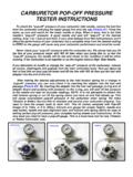
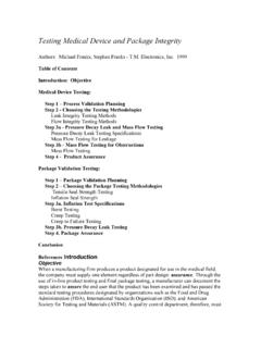
9 The later alternative voltage sources may include VLF, damp alternating voltage, or impulse voltage. Both on-line and off-line PD energization methods have advantages and disadvantages. There are also different types of partial dis-charge detection methods, one using the time domain and the other the frequency domain. Both types can locate the source of the partial discharge. All energization and detec-tion methods are meant for Type 2 diagnostic Testing . The ability of partial discharge Testing to assess the future performance of a cable system is continuously improving. The best accuracy in assessing the future performance is achieved on very good or very bad cable systems. Further Fall 2006 NETA WORLD Figure 2 Ultrasonic detector used for locating serious PDimprovements may occur as more data are collected, test and analysis procedures are standardized, and if measurements on particular cable circuits are repeated on a periodic basis, , Testing for Metallic Shield CorrosionBefore leaving the work of the ICC, I must discuss Field Testing of the cable metallic shield or concentric neutral (in utility cables).
10 It has been shown that corrosion of the shield can lead to partial discharges and eventually failure as in Figure 1. This is particularly true in unjacketed but also in jacketed cables in industrial plants. WG C7 has com-pleted work on IEEE P1617, Draft Guide for Detection, Mitigation and Control of Concentric Neutral Corrosion in Medium- Voltage Underground Cables, presently in bal-loting. This document covers a number of useful techniques for detecting, evaluating, and locating corroded or broken shields. Methods include time domain reflectometry (TDR), resistance measurement, and surface potentials methods. Although corrosion in the shield may lead to discharges that can be detected with PD Testing , the methods in this guide may find shield problems before PD and subsequent damage occur.