Transcription of FIELDVUE DVC5000 Series Digital Valve Controller
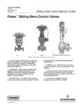
1 January 2001 Bulletin : DVC5000 . FIELDVUEr DVC5000 Series Digital Valve Controller DVC5000 Series Digital Valve controllers (figures 1 and 2) are communicating, microprocessor-based current to pneumatic instruments. In addition to the traditional function of converting a current signal to a pressure signal, these instruments, using HART. communications protocol, provide easy access to information critical to process operation. Tables 1 and 2 list the information that is accessible through FIELDVUE ValveLink software or the Rosmount Model 275 HART Communicator, shown in figure 6. Much of the information is also available on a HART.
2 Compatible distributed control system. W6164 B/IL. Because the Digital Valve Controller receives feedback DVC5000 Series Digital . Valve Controller . of the Valve travel position, the instrument can not only diagnose itself but also the Valve and actuator on which it is mounted. This provides you with very cost effective maintenance information, so that required maintenance can be performed on the instrument and Valve when there really is a need. Wiring is economical because DVC5000 Series Digital Valve controllers use two-wire 4 to 20 mA loop power. This provides for low cost replacement of existing analog instrumentation and avoids the high cost of running separate power and signal wiring.
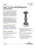
3 Features W6164/IL. TYPE DVC5020 Digital Valve . Controller MOUNTED ON. D Improved Process Control Two-way Digital ROTARY ACTUATOR. communication provides current Valve conditions. You can rely on this real-time information to make sound process management decisions. By analyzing Valve W6341/IL. dynamics with AMS ValveLink software, you can TYPE DVC5010 Digital Valve . identify those control areas that need improvement Controller MOUNTED ON. and maintain a high level of system performance. sliding stem ACTUATOR. Figure 1. FIELDVUE DVC5000 Series Digital Valve Controllers (continued on page 3).
4 D200440X012. Bulletin : DVC5000 . Specifications Available Configurations At bar (100 psig) supply pressure: Less than Type DVC5010: sliding - stem applications normal m3/hr (34 scfh). Type DVC5020: Rotary and long-stroke Maximum Output Capacity(2). sliding - stem applications At bar (20 psig) supply pressure: normal Type DVC5030: Quarter-turn rotary applications m3/hr (285 scfh). Type DVC5040: sliding - stem application Fisher At bar (60 psig) supply pressure: normal Controls System 9000 actuator m3/hr (658 scfh). DVC5000 Series Digital Valve controllers mount on Independent Linearity(1).
5 Fisher Controls and other manufacturers' rotary and of output span, typical sliding - stem actuators. Electromagnetic Interference (EMI). Input Signal These instruments have the CE mark in accordance with the Electromagnetic Compatibility (EMC). Point-to-Point: Directive. They meet the requirements of Analog Input Signal: 4 to 20 mA dc, nominal EN50081-1 (emissions for light industry) and Minimum Voltage Available at instrument terminals EN50082-2 (immunity for industrial environment). must be volts dc for analog control, 12 volts dc for HART communication (see instrument Electrical Classification instruction manual for details) Hazardous Area: Explosion-proof, intrinsically Minimum Control Current: mA safe, Division 2, and flameproof constructions are Minimum Current w/o Microprocessor Restart: available to CSA, FM, CENELEC, and SAA.
6 MA standards. Refer to the hazardous-area Maximum Voltage: 30 volts dc classification bulletins. Overcurrent Protection: Input circuitry limits current Electrical Housing: Meets NEMA 4X, IEC 529. to prevent internal damage IP65. Reverse Polarity Protection: No damage occurs from reversal of loop current Connections Supply Pressure: 1/4-inch NPT female and Multi-drop: integral pad for mounting Type 67 CFR regulator Instrument Power: 12 to 30 volts dc at Output Pressure: 1/4-inch NPT female approximately 8 mA Tubing: 3/8-inch metal, recommended Reverse Polarity Protection: No damage occurs Vent (pipe-away): 1/4-inch NPT female from reversal of loop current Electrical: 1/2-inch NPT female conduit connection, M20 adaptor optional Output Signal(1).
7 Operating Ambient Temperature Limits Pneumatic pressure as required by the actuator, up 40 to 80_C ( 40 to 175_F). to 95% of supply pressure. Minimum Span: bar (6 psig) Construction Materials Maximum Span: 6 bar (90 psig) Housing, module base, and terminal box: ANSI. Action: Direct only low copper aluminum alloy Cover: Valox Supply Pressure(1) Elastomers: Nitrile Minimum and Recommended: bar (5 psig) stem Travel higher than maximum actuator requirements DVC5010: 0 to 102 mm (4 inches) maximum Maximum: bar (100 psig) or maximum pressure 0 to mm (3/8 inches) minimum rating of the actuator, whichever is lower.
8 DVC5020: 0 to 606 mm (23-7/8 inches) maximum Steady-State Air Consumption(1),(2) Shaft Rotation (DVC5020 and DVC5030). 0 to 50 degrees minimum At bar (20 psig) supply pressure: Less than 0 to 90 degrees maximum normal m3/hr (10 scfh). At bar (35 psig) supply pressure: Less than Mounting normal m3/hr (15 scfh) Designed for direct actuator mounting. For At bar (60 psig) supply pressure: Less than weatherproof housing capability, mount the normal m3/hr (22 scfh) instrument upright to allow the vent to drain. (continued). 2. Bulletin : DVC5000 . Specifications (continued). Dimensions Weight See figures 9 and 10.
9 For dimensions of a Type Less than kg (6 lbs). DVC5040 Digital Valve Controller , see Bulletin Options :FloVue. J Standard Diagnostics or J HART. communicating; J Supply and output pressure gauges or J tire valves; J Integrally mounted filter regulator 1. These terms are defined in ISA Standard 2. Normal m3/hr Normal cubic meters per hour (0_C, bar, absolute); Scfh Standard cubic feet per hour (60_F, psia). and installation cost savings by replacing other devices in the process loop, such as positioners and limit switches. Because the Digital Valve Controller is loop powered, it can replace analog instrumentation in new or existing installations, no additional wiring is required.
10 D Built to Survive Field-tough DVC5000 Series Digital Valve controllers have fully encapsulated printed wiring boards that resist the effects of vibration, temperature, and corrosive atmospheres. As shown in figure 7, a separate weather-tight field wiring terminal box isolates field wiring connections from other areas of the instrument. D Increased Uptime With the self-diagnostic capability of DVC5000 Series Digital Valve controllers, you can answer questions about a Valve 's performance, without pulling the Valve from the line. You can compare the present Valve /actuator signature (bench set, seat load, friction, etc.)