Transcription of FIGURE 100A 1-PIECE BALL VALVE
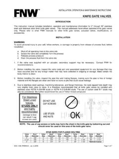
1 INSTALLATION, OPERATION & MAINTENANCE INSTRUCTIONS FIGURE 100A 1-PIECE ball VALVE DOC: IOM_FNW100A_ ver_3-2011 Page 1 of 4 INTRODUCTION This instruction manual includes installation, operation and maintenance information for the FIGURE 100A 1-PIECE 1000 CWP, threaded end (NPT) ball VALVE . INSTALLATION WARNING To avoid personal injury to your self, fellow workers, or damage to property from release of process fluid, before installation: a. Shut off all operating lines to the VALVE site b. Isolate the VALVE site completely from the process c. Release process pressure d. Drain the process fluid from the VALVE site 1. Remove the protective plastic cap from threaded ends and clean or flush the VALVE . 2. Before installing the VALVE , inspect the VALVE body port and associated equipment for any damage that may have occurred and for any foreign matter that may have collected in shipping or storage.
2 Make certain the body interior is clean. 3. Before installing the VALVE , inspect the pipe line and mating pipe threads, making sure the pipe is free of foreign material and the threads are clean and have no burrs or pits that could cause leakage. 4. Cycle the VALVE a couple of times before installation. valves that are tested to MSS SP-110 may have water trapped between the ball and body cavity. This can be removed by partially opening the VALVE , exposing the cavity to the through port of the ball . Allow the water to drain out. 5. Use applicable sealant ( - PTFE tape, high temperature pipe seal, etc.) to seal threaded ends on the pipeline. 6. Apply a pipe wrench to the hexagon end of the VALVE where the pipe is being installed.
3 Turn the pipe into the VALVE . Do not turn the VALVE onto the pipe, use the opposite end of the VALVE , or use the handle to tighten the assembly as damage to the VALVE may occur. 7. Clean/flush the pipeline and leak test the system prior to using. OPERATION 1. Ensure that the VALVE materials are compatible with the service and that the operating characteristics are below the VALVE maximums. 2. Fluids containing particles or coagulating agents are not acceptable as they can reduce the life of the seats and cause the torque to increase dramatically. 3. Care must be taken if throttling the VALVE (operation in partially open position). Critical pressure drops and high flow rates can decrease the life of, or damage, the seats.
4 For optimum operation, open/close applications are recommended. 4. The VALVE comes standard with a locking device. Slide the locking plate up the lever before operating. Open and close the VALVE by turning the handle one-quarter turn (90 ). 5. The VALVE is in the open position when the handle is parallel to the pipe, and in the closed position when perpendicular to the pipe. INSTALLATION, OPERATION & MAINTENANCE INSTRUCTIONS FIGURE 100A 1-PIECE ball VALVE DOC: IOM_FNW100A_ ver_3-2011 Page 2 of 4 MAINTENANCE VALVE parts are subject to normal wear and must be inspected and replaced as necessary. Inspection and maintenance frequency depends on the severity of the service conditions.
5 This section includes instructions for packing adjustments, repacking, seat replacement and seating adjustment. WARNING To avoid personal injury, fellow workers, or damage to property from release of process fluids, before installation: a. Shut off all operating lines to the VALVE . b. Isolate the VALVE completely from the process. c. Release process pressure. d. Drain the process fluid from the VALVE . 1. ball valves , if properly used, do not require internal lubrication or maintenance. However, a visual inspection should be part of a regular maintenance program. A higher frequency of inspection is recommended for valves operating under extreme conditions. Also, for proper operation it is recommended that the VALVE be opened and closed at least twice a year.
6 2. Before any maintenance, open and close the VALVE at least once to release the pressure completely from the VALVE body. 3. For stem packing leaks, with the lever locking device engaged, use a crescent wrench to turn the stem nut clockwise at 30 to 60 intervals until the leak stops. If the stem nut can not be turned clockwise any further, or if the stem packing continues to leak, it will have to be replaced or repaired. NEVER REPLACE VALVE PACKING WHILE THE VALVE IS IN SERVICE. 4. The VALVE can be rebuilt by using a Soft Goods repair kit from FNW. Disassembly A. Place the VALVE in a vise in the closed position. Do not over-tighten the vise or the VALVE may be deformed. B. Remove the stem nut (11), stem washer (10), handle (13), and gland (9).
7 C. With a hex wrench, remove the end cap (2), seat-2 (14), and the body gasket (5)(1-1/4 ~2 only). D. Remove the ball (3) and seat-1 (4). E. Push the stem (6) down through the body (1), and then remove the thrust washer (7) from the stem. F. Remove the packing (8) from the body. Assembly A. Rebuild the VALVE by using all the replacement parts of the rebuild kit. B. Ensure that all parts are clean and undamaged. C. Assemble the VALVE in reverse order of the disassembly instructions, except install the packing after the stem is inserted. It is recommended to cycle and test the VALVE prior to resuming service. After reinstallation into the piping system, it may be necessary to adjust the stem nut/packing gland as described in step 3.
8 INSTALLATION, OPERATION & MAINTENANCE INSTRUCTIONS FIGURE 100A 1-PIECE ball VALVE DOC: IOM_FNW100A_ ver_3-2011 Page 3 of 4 11L11098324657WH Ref. No. DescriptionMaterial 1 BodyASTM A351 Gr. CF8M Stainless2 End CapASTM A351 Gr. CF8M Stainless3 Ball316SS Stainless4 Seat - 1 RTFE5 Body Gasket*PTFE6 Stem316SS Stainless7 Thrust WasherPTFE8 Stem PackingPTFE9 Gland304SS Stainless10 Stem Washer304SS Stainless11 Stem NutASTM A194-8 Stainless12 Handle SleeveVinyl Plastic13 Locking Handle304SS Stainless14 Seat - 2 RTFE* 1-1/4 ~2 only, gasket is integral to seat-1 on smaller sizes. INSTALLATION, OPERATION & MAINTENANCE INSTRUCTIONS FIGURE 100A 1-PIECE ball VALVE DOC: IOM_FNW100A_ ver_3-2011 Page 4 of 4 WARRANTY 1. LIMITED WARRANTY: Subject to the limitations expressed herein, Seller warrants that products manufactured by Seller shall be free from defects in design, material and workmanship under normal use for a period of one (1) year from installation but in no case shall the warranty period extend longer than eighteen months from the date of sale.
9 This warranty is void for any damage caused by misuse, abuse, neglect, acts of God, or improper installation. For the purpose of this section, Normal Use means in strict accordance with the installation, operation and maintenance manual. The warranty for all other products is provided by the original equipment manufacturer. 2. REMEDIES: Seller shall repair or replace, at its option, any non-conforming or otherwise defective product, upon receipt of notice from Buyer during the Manufacturer s warranty period at no additional charge. SELLER HEREBY DISCLAIMS ALL OTHER EXPRESSED OR IMPLIED WARRANTIES, INCLUDING, WITHOUT LIMITATION, ALL IMPLIED WARRANTIES OF MERCHANTABILITY AND FITNESS OR FITNESS FOR A PARTICULAR PURPOSE.
10 3. LIMITATION OF LIABILITY: UNDER NO CIRCUMSTANCES SHALL EITHER PARTY BE LIABLE TO THE OTHER FOR INCIDENTAL, PUNITIVE, SPECIAL OR CONSEQUENTIAL DAMAGES OF ANY KIND. BUYER HEREBY ACKNOWLEDGES AND AGREES THAT UNDER NO CIRCUMSTANCES, AND IN NO EVENT, SHALL SELLER'S LIABILITY, IF ANY, EXCEED THE NET SALES PRICE OF THE DEFECTIVE PRODUCT(S) PURCHASED DURING THE PREVIOUS CONTRACT YEAR. 4. LABOR ALLOWANCE: Seller makes NO ADDITIONAL ALLOWANCE FOR THE LABOR OR EXPENSE OF REPAIRING OR REPLACING DEFECTIVE PRODUCTS OR WORKMANSHIP OR DAMAGE RESULTING FROM THE SAME. 5. RECOMMENDATIONS BY SELLER: Seller may assist Buyer in selection decisions by providing information regarding products that it manufacturers and those manufactured by others.