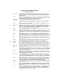
Transcription of Figure 9 Downhole WIW Wellbore Schematic Open Hole
1 TYPICAL open hole WATER INJECTION WELL (WIW) Downhole DIAGRAMWELL NAME: Tundra Ewart Unit 4 HZNTL open hole WIW WELL LICENCE:Prepared by WRJ(average depths)Date: 2012 Elevations :KB[m]KB to THF [m]TD [m] [m]CF (m)PBTD [m]Current Perfs: open Perfs:toKOP:700 m MDTotal Intervalto TubularsSize [mm]Wt - Kg/mGradeLanding Depth [mKB]Surface - ST& Csg (if run) & - LT& hole or - or of Tubing Installation:LengthTop KBCorrosion Protected ENC Coated Packer (set within 15 m of Intermed Csg shoe) mm or 73 mm TK-99 Internally Coated Tubing SC = 140mKBTK-99 Internally Coated Tubing Pup JtCoated Split DognutAnnular space above injection packer filled with inhibited fresh waterBottom of Tubing mKBRod String :Date of Rod Installation:Bottomhole Pump: Directions: KOP = ~ 700 mMDInhibited Annular FluidInjection Packer set within 15 m of Intermediate Casing Shoe Intermediate Casing ShoeOpen hole FracturesTundra Oil And Gas Partnership0