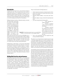
Transcription of Figure BI-6: Development paths for today’s drill bits.
1 Copyright 2014 IADC Drilling Manualhandling the transitions without the vibrations of a PDC, and in those where the PDC is not consistent enough to make the required interval reliably. An adjustable DOC control feature is being introduced which will alleviate some of the concerns mentioned with earlier technologies. Further, new cutter technology is emerging with cutters which are free to rotate in a PDC bit, and others have innovative chamfers or a contoured face to control chip flow and temperature. A resurgence in the science of the HTHP apparatus for making PDC cutters has led to substantial improvements in the base underlying cutter bit basicsThe drilling bit industry is changing rapidly in the areas of manufacturing technology and the use of new materials. Computers have also caused dramatic changes in the drill -ing bit manufacture process, as today the use of bottomhole simulation software in order to have a new bit design virtu-ally tested before it gets manufactured is a very common practice in this industry.
2 HistoryThe drill bit history timeline actually stars about 5,000 years ago in ancient China. There is some historical evidence indi-cating that water wells were drilled using cable drilling tech-nology with percussion bits . More recently: 1845: Pierre Pascal Fauvelle invented the rotary drilling system. It was used in the early years of the oil industry in some of the oil-producing countries in Europe. Fish tail-type bits were used ( Figure BI-2a); 1859: Edwing Laurentine Drake drilled the first oil commercial well in Titusville, Pennsylvania. Percussion-type bits were used ( Figure BI-2b); 1900: The rotary drilling system was in general use in Texas; 1901: On January 10 a well at the Spindle Top oilfield, a salt-dome structure located in south Beaumont, Texas, was drilled, marking the birthdate of the modern petroleum industry; 1909: Howard R. Hughes granted US Patent 930759 on August 10 for two cone bits ( Figure BI-3); 1910: Howard R.
3 Hughes granted US. Patent 959540 on May 31 for a three-cone roller bit ( Figure BI-4); 1925: Cutting structures with intermesh were invented; 1928: Use of tungsten carbide hard-facing first used in the drilling industry; 1939: Offset criteria was introduced to roller-cone bit design; 1940: Natural diamond bits introduced to the market; 1951: TCI first used in roller-cone bits ; 1953: General Electric Company created synthetic diamond crystals ( Figure BI-5); 1963: Sealed bearing roller-cone bits first used; 1969: O-ring sealed journal bearing introduced; 1976: The PDC cutter was introduced by General Electric; 1986: Diamond-enhanced inserts (DEI) introduced on roller-cone bits by MegaDiamond; 1994: PDC technology introduced the non-planar interface (NPI) between tungsten carbide substrate and BITSBI 5 Figure BI-6: Development paths for today s drill 2014 IADC Drilling Manualdiamond table.
4 Diamond table thickness was increased to maximize wear resistance and cutter life; 1995: Polished cutters, stress engineered cutter placement and application-specific cutters introduced commercially; 2003: Surface-leached PDC cutters commercialized; 2003: Depth of cut control for steerable PDC introduced; 2013: Rotating PDC cutter and a PDC cutter with a contoured face to improve chip flow and run bits classification There are two big groups of drilling bits , including its respec-tive divisions and sub-divisions, as follows: The PDC bits can be sub-classified as: Matrix-body PDC; Steel-body same type of sub-classification applies to bi-center bits : Matrix-body bi-center; Steel-body , impregnated bits can be sub-classified as: Conventional impregnated matrix; Impregnated inserts or : Matrix is manufactured from a tungsten carbide pow-der and metallic basicsBased on the drilling mechanics differences between roller cone bits and diamond bits , different design concepts apply for each group of bits .
5 Roller-cone bitsThere are three basic design factors for roller-cone bits : Cone offset; Journal (bearing pin) angle; Cone The bit cone s offset is defined as the horizontal distance between the axis of the bit and a vertical plane through the axis of the journal. Offset is established by moving the centerline of a cone away from the centerline of the bit in such a way that a ver-tical plane through the cone centerline is parallel to the ver-tical centerline of the bit. BI 6 BITSF igure BI-7: The bit cone s offset is the horizontal distance between the bit axis and a vertical plane through the axis of the journal. Soft formations usually experience a high offset, while hard formations usually have a low offset. Courtesy BI-8: The top image shows a low offset, while the lower drawing shows a high offset. Notice the difference between the centerline and the offset on each cone.
6 Courtesy formations usually experience a high offset (3 8 in.), while hard formations usually have a low offset (1 32 in.).Soft formation bits use high offsets values to increase this cutting action and thus increase ROP, while harder bits use lower offsets values to reduce cutter wear induced by the sliding action. These images show a low offset (up) and a high offset (down). Notice the difference between the centerline and the offset on each cone geometry directly affects increases or decreases in either journal or offset angles and a change in one of them requires a compensating change in the (bearing pin) angleThe journal angle is the angle formed by a line perpendicular to the axis of the bit and the axis of the journal. Journal angle influences the design of many key bit features, including: Intermesh depth; Insert projection and milled tooth depth; Heel surface length and angle; Gauge contact and length; Cone diameter; Cone shell thickness; Bearing space availability; Leg also affects the relationship between scraping and crush-ing actions produced by the cutting elements of the bit.
7 Soft formations: low journal angle Generally, bits with relatively small journal angles, 30 -33 , are best suited for drilling in softer formations that require lower weight on bit (WOB). These formations require goug-ing and scraping formations: high journal angleLarger journal angles, 34 -39 , are better when drilling in harder formations that require higher WOB amounts. Hard formations require a chipping and crushing 7 Copyright 2014 IADC Drilling ManualFigure BI-10 (top and center right): Usually bits with smaller journal angles (30 -33) are best for drilling softer formations requiring lower WOB. Conversely, larger journal angles are better for harder formations requiring higher WOB. Courtesy BI-9 (above): The journal angle is formed by a line perpendicular to the bit axis and the journal axis. Courtesy 8 BITSC opyright 2014 IADC Drilling ManualDesign factors summaryFigure BI-11 identifies the basic design factors associated with designing a bit for a particular type of formation.
8 For example, in a very soft formation, the teeth of the bit are spaced further apart, longer in length and provide more gouging-scraping action; the journal angle is lower, while the offset is and pressure compensation systemRoller coneThe lubrication and pressure compensation system equal-izes pressure across the seal and provides lubricant to op-timize temperature and load pressure within the bearing system. Roller-cone bits have one of the highest unit loads of any bearing and require specialized grease. Each drill bit manufacturer has developed custom-engineered roller cone bearing grease compatibility with all bearing components. The grease has been designed to have higher heat capaci-ty, greater resistance to oxidation, and higher load capacity Figure BI-12: Roller-cone bits boast one of the highest unit loads for any bearing and require specialized BI-13: Seals contribute significantly to the effectiveness of the lubrication and pressure compensation system by preventing drilling contaminants from entering the bearings.
9 Non-sealed bearing designs allow mud to enter the bearing to cool and lubricate, but suffer shorter bearing life than sealed bearings. Figure BI-11: The basic design factors associated with designing bits for particular formation types. In a very soft formation, for instance, the bit teeth are spaced farther apart, are longer and gouge and scrape more than chip or crush. Courtesy 9 Copyright 2014 IADC Drilling Manualthan conventional bearing greases. Collectively these char-acteristics minimize wear and friction and extend the life of the bearing pressure compensation system serves to accommodate grease expansion, cone movement and annulus pressure and maintain a stable environment for the bearing system. The seal contributes significantly to the effectiveness of the lubrication and pressure compensation system as its dy-namic properties keep drilling contaminants from entering the pressure compensation system has a diaphragm that moves inwards to equalize internal pressure with the outside pressure from the annulus or changes in volume from cone movement.
10 The diaphragm moves outward to increase the internal volume from grease expansion and cone movement to equalize with external pressure. In doing so, grease can vent through the diaphragm into the annulus to equalize the bearing designs incorporate solid lubrication com-ponents such as thrustwasher or hardmetal inlays; others incorporate a silver-plated bearing surface. These compo-nents serve to form a dissimilar material system that miti-gates adhesive wear when carrying the thrust component of the bearing load. These run against Stellite inlays, in many cases, which also provide a dissimilar material system that mitigates adhesive wear. The inlays have higher wear resis-tance properties than steel so as to reduce bearing all roller cone drill bits have sealed bearings. Non-sealed bearing designs allow mud to enter the bearing for cooling and lubrication. Non-sealed designs have a shorter bearing life than sealed bearings as mud contains particles that can cause excessive wear to the bearings therefore shortening the bearing in comparison to sealed designs.