Transcription of Filter Clogging Indicators
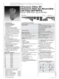
1 1E Clogging Indicators1. TECHNICAL GENERALHYDAC Clogging Indicators are designed to indicate visually and/or electrically when the Filter elements must be cleaned or changed. The operational safety of a system and efficient utilisation of a Filter element can only be guaranteed if Clogging Indicators are on the type of Filter , vacuum, return line or differential pressure Clogging Indicators are SEALSNBR (= Perbunan) or V (= Viton) INSTALLATIONSome users install filters without Clogging Indicators and prefer instead to replace or clean the elements according to a specified time schedule or according to a set number of operating hours.
2 However, this involves some risk. Fitting a Clogging indicator has two main advantages: The operator no longer has to estimate when the element is clogged. The unnecessary costs of changing the element too early are standard filters can be fitted with a Clogging indicator at any time, by simply screwing it DESIGNR eturn line indicatorsThese are used for return line and suction filters. In return line filters they react to the increasing static pressure before the Filter element, and in suction filters to the decreasing pressure after the Filter element, which is caused by increasing contamination.
3 Differential pressure indicatorsThese are used for all inline filters and react to the increasing pressure differential caused by increasing contamination of the Filter simplest installation of the differential Clogging indicator is via G " cavity (according to HYDAC works standard HN 28-22)The differential pressure indicator type V02 is piped up SPECIAL INDICATORSM obile indicatorsThese Indicators have been developed for special applications and are fitted with AMP Junior Power Timer, AMP superseal or Deutsch indicatorsThese Indicators are used in potentially explosive locations and are subject to the ATEX Equipment Directive 2014/34/EU and the ATEX Operator Directive 1999/92 and CSA indicatorsIndicators which are exported to the USA and Canada often require classification according to current UL and CSA standards.
4 The UL and CSA symbols are found on many products, particularly in the field of electrical sideContaminated- TABLE OF CONTENTSC ontentsPage:Quick selection table: by indicator type 2 Quick selection table: by Filter type 3 Standard Indicators Vacuum Return line Differential pressure 4 7 21 Indicator ( ) for Condition Monitoring 24 Mobile Indicators Return line Differential pressure 29 31 ATEX Indicators Return line Differential pressure 34 36UL/CSA Indicators Differential pressure Return line 38 39 Model code - Standard40 Adapters42 DESINA Specification442E QUICK SELECTION TABLES FOR Clogging Indicators BY INDICATOR TYPEP lease select the type of indicator you require from the indicatorPermitt.
5 Operating pressure [bar]Return line indicatorPermitt. operating pressure [bar]Differential pressure indicatorPermitt. operating pressure [bar]VisualB 7 210/420BF 40BM 7 210/420E 7 (11)ES 7K * *R 7 UBM 0UE 0 UED 0V 100 ElectricalC 40 210/420D 40 210/420F 40LE 7 420LZ 7 420UF 0VE 100VZ 100 ElectronicGC 7 420GW 25 MobileCD 210CJ 210/420CM 40 210CS 210/420FD 40FJ 40FS 40 LEM 7 420M 210 ATEXB 7 210/420C 40 210/420UL Approval (=CRUUS)C 210/420 CSA ApprovalC 40* Dependent on BY Filter TYPEP lease select the Clogging indicator required for your Filter from the ) Can only be used for suction operation 2)
6 Use VMF 16 onlyTypeBFBLBLTDF DFFDFDK DFDKNDF MA/QE MPDFMDFN DFNFDFP DFPF DFFXDFZELFFLNFLND FMNDHDF HDFFHDPHFMLF LFFLFMLFN LFNFB BFBM EESK R/RSUBM UE 1) 1)UED VC D FLE LZ UF 1) 1)VEVZGC GWCD CJ/CS CM FJ/FD/FSM LEM TypeLPFMDFMFMFDMFMMFXNFNFDRFRFDRFLRFLDRF NRFNDRFMRKMSFSFFSFMB BF BM E 2) 2) ES KR/RS UBMUE 1) 1) 1) 1)
7 V C D F LE LZ UF 1) 1) 1) 1) VE VZ GC GW CD CJ/CS CM FJ/FD/FS M LEM 4E VACUUM INDICATORSVMF x of indicationvisual-analogue, scale indicationWeight53 gPressure setting or indication range-1 bar to 0 bar Permitt.
8 Operating to 0 bar continuousPermitt. temperature range-20 C to +60 CThreadG 1/8 Max. torque10 NmSwitching type-Max. switching voltage-Electrical connection-Max. switching voltage at resistive load-switching capacity-Protection class to DIN 40050-Order exampleVMF 1 x of indicationvisual-analogue, scale ring 1/8O-ring gPressure setting or indication range-1 bar to 0 barPermitt. operating to 0 bar continuousPermitt. temperature range-20 C to +60 CThreadG 1/2 Max. torque30 NmSwitching type-Max. switching voltage-Electrical connection-Max. switching voltage at resistive load-switching capacity-Protection class to DIN 40050-Order exampleVR 1 x of indicationvisual-analogue, scale indicationWeight133 gPressure setting or indication range-1 bar to 0 barPermitt.
9 Operating to 0 bar continuousPermitt. temperature range-20 C to +60 CThreadG 1/2 Max. torque33 NmSwitching type-Max. switching voltage-Electrical connection-Max. switching voltage at resistive load-switching capacity-Protection class to DIN 40050-Order exampleVRD 1 x of indicationelectrical switchWeight154 gPressure setting or indication bar barPermitt. operating pressure40 barPermitt. temperature range-30 C to +100 CThreadG 1/2 Max. torque33 NmSwitching typeN/O contact (N/C as an option)Max. switching voltage48 VElectrical connectionthreaded connectionMax. switching voltage at resistive load60 W = 100 VA ~switching capacityohmic A at 24 V = ohmic A at 42 V ~Protection class to DIN 40050IP 65, terminals IP 00 Order exampleVRD x of indicationelectrical switchWeight75 gPressure setting or indication bar barPermitt.
10 Operating pressure40 barPermitt. temperature range-30 C to +100 CThreadG 1/8 Max. torque10 NmSwitching typeN/O contact (N/C as an option)Max. switching voltage48 VElectrical connectionthreaded connectionMax. switching voltage at resistive load60 W = 100 VA ~switching capacityohmic A at 24 V = ohmic A at 42 V ~Protection class to DIN 40050IP 65, terminals IP 00 Order exampleVMF x of indicationelectrical switchWeight146 gPressure setting or indication bar barPermitt. operating pressure40 barPermitt. temperature range-30 C to +100 CThreadG 1/2 Max. torque30 NmSwitching typeN/O contact (N/C as an option)Max.