Transcription of Finite Element Analysis Using MATLAB Toolbox
1 AppendixDFinite Element Analysis UsingMATLAB ToolboxIn this section, a MATLAB3toolbox CALFEM4is introduced. This Toolbox is developedby Lund University in 1999 and can be downloaded free of charge from CALFEM provides functions that can be used for Finite elementanalysis of a variety of structures. Compared to other Finite Element programs, this tool-box has many advantages for education. Many commercial programs automatically per-form Finite Element process. Thus, the users do not understand the process of constructingelement stiffness matrices, assembling them, and applying boundary conditions. In thistoolbox, however, the users must provide every step of Finite Element process.
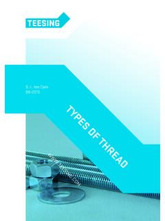
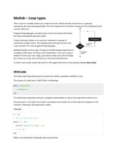
2 The tool-box then provides functions that can perform particular step of Finite Element general, MATLAB toolboxes are stored in the Toolbox folder in MATLAB instal-lation folder. In order to access the Toolbox , the user must provide path information usingFile, Set Path ..command from the main menu. Once the CALFEM folder location isstored in MATLAB paths, the user can access CALFEM functions anywhere. Type help spring1e in MATLAB window in order to test accessibility. If the path isproperly assigned, then MATLAB should return help content of spring1e function,as shown in Figure Finite Element Analysis OF BAR AND TRUSST hree Uniaxial Bar ElementsIn this section, the uniaxial bar problem in Example will be solved Using theMATLAB Toolbox .
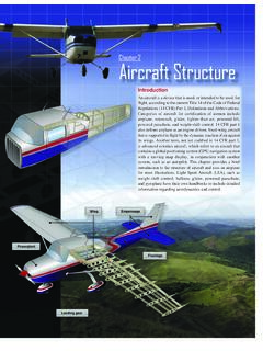
3 The problem consists of four nodes and three elements, as shown inFigure In one dimensional problems, each node has a single DOF, and nodes areKe=spring1e(ep) PURPOSEC ompute Element stiffness matrix for spring : ep = [k]; spring stiffness or analog quantityOUTPUT: Ke : stiffness matrix, dim(Ke)= 2 x 2 Figure content of spring1e function3 MATLAB is the trademark of The MathWorks, A Finite Element Toolbox for MATLAB , Lund University, 1999, Web: by elements. The information of the connectivity is defined by the followingarray:Edof=[1 1 2;223;3 2 4];( )The first column ofEdofarray represents Element numbers, and the second and thirdcolumns represent the DOF of Nodesiandj, respectively.
4 For example, Element 2 (thesecond row) connects Nodes 2 and , the global stiffness matrix and force vector are defined:K=zeros(4,4);F=zeros(4,1);F(1)=4 0;( )Since there are four nodes and each node has a single DOF, the dimension of the globalstiffness matrix is 4 4. Initially, components of the stiffness matrix and force vector areset to zero. In the last line of ( ), the external force 40 N is applied to Node 1. Note thatthe reaction forces are not specified in the global force , the Element stiffness matrices are constructed Using the given spring this purpose, spring1e function is used:ep1=50;ep2=30;ep3=70;Ke1=spring1e(e p1);Ke2=spring1e(ep2);Ke3=spring1e(ep3); ( )The three variables,ep1,ep2, andep3, represent the axial rigidity (or, spring constants)of each Element .
5 When a uniaxial bar with constant cross-section is used, the axialrigidity,EA=L, can be used as the spring constant. Using these spring constants, the spring1e function calculates the 2 2 stiffness matrix that corresponds to Eq. ( )in Chapter 2. For example,Ke3contains the 2 2 stiffness matrix for Element 3. Thisstep must be repeated for all elements. When the material properties are the same, theprogram can be simplified by Using thefor endloop command in the Element stiffness matrices are obtained, they are assembled to form theglobal stiffness matrix Using assem function:K=assem(Edof(1,:),K,Ke1);K=asse m(Edof(2,:),K,Ke2);K=assem(Edof(3,:),K,K e3);( )Figure dimensional structure with three uniaxial bar elements392 Chapter D Finite Element Analysis Using MATLAB ToolboxIn order to assemble the Element stiffness matrix into the global stiffness matrix, it isnecessary to specify the relation between the local DOFs in the global DOFs.
6 This infor-mation is stored inEdofarray. Thus, the first argument of assem function is the rowofEdofarray. Then, the first line of ( ) will copy 2 2matrixKe1into the globalstiffness matrixKin the location that is specified in the first row ofEdofarray. The resultis returned to the global stiffness matrixKso that the matrixKcontains the accumulateddata from all global stiffness matrixKin ( ) is singular because there is a rigid body motionin the system. In order to remove the rigid body motion, the boundary condition must beapplied. The displacement boundary condition is specified bybc=[30;40];( )The first column ofbcarray represents the DOF number and the second column is theprescribed value of the DOF.
7 Since Nodes 3 and 4 are fixed, zero values are provided forboth the global stiffness matrix and global force vector, the unknown DOF can besolved Using solveq function:Q=solveq(K,F,bc);( )In this particular implementation, the reduced stiffness matrix is not constructed explic-itly. The prescribed DOFs are deleted during the matrix solution phase. The results ofthe matrix solution (nodal displacement) are stored in the variableQ. For this problem,the stored nodal displacements areQ f1:2;0:4;0:0;0:0g. Note that Nodes 3 and 4have zero nodal displacement that is calculated in ( ) can be used to calculate the ele-ment force. For that purpose, the Element displacement needs to be extracted from theglobal displacementQ,ased1=extract(Edof(1,: ),Q);ed2=extract(Edof(2,: ),Q);ed3=extract(Edof(3,:),Q);( )The arrayEdofis used to find the location of those nodes in the Element from the globalnode numbers.
8 For example,ed2contains the displacement of Nodes 2 and 3. Using theelement nodal displacements and spring constant for the Element , the Element force canbe calculated by calling spring1s function:es1=spring1s(ep1,ed1);es2=sprin g1s(ep2,ed2);es3=spring1s(ep3,ed3);( )The Element force corresponds to that in Eq. ( ). It is positive when the force is tensionand negative when compression. For this problem, the Element forces arees1 40 N;es2 12 N, andes3 28 provides the list of MATLAB program that can solve the same problem inExample Finite Element Analysis of Bar and Truss393 The above example is the classical Finite Element Analysis procedure. As can be seen,the formulation is based on the general force displacement equations of a single one dimensional truss Element .
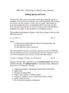
9 The two force member Element or truss Element is the sim-plest type of Element used in Finite elementanalysis. The procedure to formulate andsolve the force displacement equation is straightforward, but somewhat tedious. In reallife applications, the use of one dimensional truss Element is rare. In the next section, wewill expand the procedure to solving two dimensional Truss ExampleIn this section, the two bar truss structure in Example is solved Using the MATLAB Finite Element program. Unlike one dimensional problem, there are two DOFs at eachnode. Two DOFs are assigned at each node in a sequence along with the node numbers,as illustrated in Figure Element connectivity array now contains four DOFs:Edof=[11234;23456];( )The first Element connects Node 1 (DOF 1 and 2) and Node 2 (DOF 3 and 4), while thesecond elements connects Node 2 (DOF 3 and 4) and Node 3 (DOF 5 and 6).
10 Table Commands forSpring Finite ElementsEdof=[1 1 2;2 2 3;3 2 4];K=zeros(4,4);F=zeros(4,1); F(1)=40;ep1=50;ep2=30;ep3=70;Ke1=spring1 e(ep1);Ke2=spring1e(ep2);Ke3=spring1e(ep 3);K=assem(Edof(1,:),K,Ke1);K=assem(Edof (2,:),K,Ke2);K=assem(Edof(3,:),K,Ke3);BC =[3 0;4 0];Q=solveq(K,F,bc);ed1=extract(Edof(1,: ),Q);ed2=extract(Edof(2,:),Q);ed3=extrac t(Edof(3,:),Q);es1=spring1s(ep1,ed1);es2 =spring1s(ep2,ed2);es3=spring1s(ep3,ed3) ;394 Chapter D Finite Element Analysis Using MATLAB ToolboxThe size of global stiffness matrix and force vector can be determined based on thetotal number of DOFs, asK=zeros(6);F=zeros(6,1);F(3)=50;( )Note that the applied force at Node 2 in thex direction, it must be assigned in the DOF the two dimensional problem, two properties are required for the Element :ep=[3e7:125 :125 pi];( )The first represents the Young s modulus, while the second for the cross-sectional length of the Element will be calculated based on the coordinates of the two one-dimensional problem, the coordinates of nodes are required in order tocalculate the length of the Element and the coordinate transformation [0 12];ey1=[0 8].