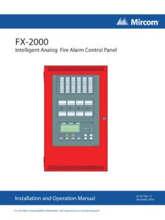
Transcription of Fire Alarm Control Panel - Mircom
1 Canada25 Interchange WayVaughan, ON L4K 5W3 Tel: 905-660-4655 Fax: 905-660-4113 Mircom 2002 Printed in CanadaSubject to change without prior Alarm Control PanelLT-2016 MIR Rev. 3 July 2010 Installation and Operation ManualAdvanced Life Safety Industrial ParkwayCheektowaga, NY 14227 Tel: 1-888-660-4655 Fax: 1-888-660-4113 Mircom Technologies of Contents1 FA-265 fire Alarm Control Unit .. features .. , Standards and Installation Requirements .. codes and standards .. Installation requirements .. Support and General Information .. Verification .. Power .. Maintenance .. 122 Preparing to Install the FA-265 fire the FA-265 .. Accessories .. Overview .. Label Insert .. Your Installation .. Specifications .. Current Ratings .. Battery calculation chart.
2 For Standby Battery Requirement .. 203 Installing the FA-265 fire Specifications .. Assembly and Modules Locations .. the FA-265 .. 244 Wiring the Specifications .. 2-Wire and 4-Wire Devices Typical Wiring .. Wiring Chart .. NAC Devices (Class A and Class B ) .. Wiring Chart .. Secur-bus Wiring Chart .. 31 Mircom Technologies Panel Sequences .. Zone fire Alarms .. Alarms .. Zone Alarms .. fire Supervisory .. / Trouble Priority .. / fire Alarm Priority .. Operation .. Troubles .. Reset Operation .. Test .. Test (Installer function only) .. operation .. B operation selections: .. A operation selections .. Function .. Relay .. Relay .. Relay (available with the RM-263 Relay Expander only).
3 386 FA-265 System Installer Programming Mode .. Using the LED Indicators to Program the System .. the Silence Trouble and Silence Alarm Controls to Program the System .. the Reset System and Lamp Test Controls .. and Exiting the System .. Function Descriptions .. Programming .. Sounding Rate Programming .. NAC Automatic Signal Silence and NAC2 Strobe Mode Programming .. Signal Silence Inhibit Timer and Walk Test Programming .. Alarms Programming .. AC Line Frequency (50 or 60 Hz) .. the Reset Programming Mode .. a Module from the System .. a Module to the System .. the System .. the Event Buffer .. 51 Mircom Technologies Startup of the to power up .. up sequence .. Operation .. the Panel .. Verification .. 548 Programming the Installer Programming Mode.
4 Programming .. Temporal/Steady Programming (Section 1) .. Auto-silence, Strobe Programming (Section 2) .. Inhibit and Walk Test Programming (Section 3) .. Programming (Section 4) .. Option (Section 5) .. 589 Appendix: ULI Compatible Smoke Compatible Smoke Detector Bases .. Compatible 4-Wire Smoke Detectors .. Compatible Horns/Strobes .. 6210 FCC Compliance Statement11 Warranty & Warning Please Read Carefully .. to Installers .. Failures .. Warranty .. Warranty .. to Void Warranty .. Procedure .. of Warranties .. of Warranty Repairs .. 69 Mircom Technologies Technologies of FiguresFigure 1 FA-265 cabinet with door closed .. 15 Figure 2 FA-265 display and controls .. 15 Figure 3 FA-265 Cabinet Overview .. 15 Figure 4 Zone Label Insert.
5 16 Figure 5 Panel Assembly and Modules Locations .. 23 Figure 6 Mounting Dimensions .. 24 Figure 7 Knockout Locations .. 24 Figure 8 FA-265 Terminals Descriptions .. 25 Figure 9 Connecting 2-Wire Alarm Initiating Devices .. 27 Figure 10 Connecting 4-Wire Smoke Detectors .. 27 Figure 11 Connecting NAC Devices (Class B ) .. 28 Figure 12 Connecting NAC Devices (Class A ) .. 28 Figure 13 Connecting Batteries .. 29 Figure 14 Connecting AC Power .. 30 Figure 15 Connecting the Alarm and Trouble Relays .. 30 Figure 16 Connecting Optional Devices .. 30 Figure 17 Locating the Walk Test Switch .. 40 Figure 18 Using the LED Indicators to Program the System .. 41 Figure 19 Using the Controls to Program the System .. 41 Figure 20 LED Indicators for Viewing the Event Buffer.
6 51 Mircom Technologies Technologies fo TablesTable 1 Electrical Specifications .. 17 Table 2 Module Current Ratings .. 18 Table 3 Battery Calculation Chart .. 21 Table 4 FA-265 Terminal Descriptions .. 26 Table 5 Zone Wiring Chart .. 28 Table 6 NAC Wiring Chart .. 29 Table 7 Secur-bus Wiring Chart .. 31 Table 8 Secur-bus Devices .. 32 Table 9 System Faults and Troubles .. 35 Table 10 LED Indicators for Zone Programming .. 43 Table 11 LED Indicators for NAC Sounding Rate Programming .. 44 Table 12 LED Indicators for NAC Auto SIlence and NAC2 Strobe Mode Programming .. 45 Table 13 LED Indicators for Signal Silence Inhibit Timer and Audible Walk Test Programming .. 46 Table 14 LED Indicators for Waterflow Alarms Programming .. 47 Table 15 LED Indicators for Reference AC Line Frequency (50 or 60 Hz).
7 48 Table 16 Removing an Module from the System .. 49 Table 17 LED Indicators for Defaulting the System .. 50 Table 18 Event Buffer Table .. 52 Table 19 ULI Compatible Smoke Detectors .. 60 Table 20 ULI Compatible Smoke Detector Bases .. 61 Table 21 ULI Compatible 4-Wire Smoke Detectors .. 61 Table 22 ULI Compatible System Sensor Horns/Strobes .. 62 Table 23 ULI Compatible Gentex Horns/Strobes .. 62 Table 24 ULI Compatible Wheelock Horns/Strobes .. 63 Mircom Technologies Technologies The FA-265 fire Alarm Control General features Five initiating device circuits, class B / style B Two notification appliance circuits, class B / style Y (Power Limited)[can be wired as one NAC, class A / style Z] One common Alarm -actuated relay, form C One common trouble-actuated relay, form C AUX+ power output, 500 mA max.
8 (Power Limited) Unswitched common and switched common auxiliary power returns Integral battery charger Cabinet with dead-front construction Transformer, mounted in the ApplicationsThe FA-265 five zone, fire Alarm Control Panel is listed for use in the following applications. Protected Premises fire Alarm SystemAnd for the following types of service:A automatic, M Manual, SS Sprinkler Supervisory, WF Codes, Standards and Installation Relevant codes and standardsThe FA-265 fire Alarm Control Panel is designed to meet the requirements of NFPA 72, 2002edition, UL 864 Rev 9, Control Units for fire Protective Systems, and in Canada, CAN/ULC-S527-99, Standard for Control Units for fire Alarm provided with this unit is intended as a guide. Installation of this equipment,optional system components, Alarm initiating devices and notification appliances must followthe manufacturer s guidelines as contained in their respective installation documents, allapplicable codes and the instructions of the Local Authority Having General Installation requirementsManufacturer s documentsWhen installing the FA-265 Control Panel , refer to this manual.
9 When installing optional systemcomponents refer to the installation documents included with those components. WhenMircom Technologies compatible Alarm initiating devices or notification appliances, refer to the installationdocuments included with those wiringField wiring recommendations in this document are intended as guidelines. All field wiringmust be installed in accordance with NFPA 70 National Electrical Code and in Canada with thestandard for installation ULC/S 524, the most current Canadian Electrical Code, with allrelevant local codes and standards, and the Authority Having Jurisdiction. Compatible devicesUse UL or ULC Listed smoke detectors and notification appliances that are compatible withthe FA-265 fire Alarm Control Panel from the lists included in this Technical Support and General InformationFor technical support call 1--888-660-4655, or email general product information visit the Mircom web site: System VerificationThe complete fire Alarm system must be verified for proper installation and operation when: the initial installation is ready for inspection by the Local Authority Having Jurisdiction; any system component is added, changed or deleted; any programming changes are made; system wiring has been altered or repaired.
10 System failure due to external influences such as lightning, water damage or extendedpower outages has Standby PowerThe FA-265 provides standby battery support for lead-acid rechargeable batteries. Therequired capacity of the standby batteries must be calculated using the charts and tableswithin this manual for the period as required by national or local codes and standards. Eventhough the calculation table within this manual includes a safety margin, lead-acid batteriescommonly used for standby can have variable capacity as a result of age and ambientconditions. Periodic inspection for damage and the batteries ability to support the attachedequipment is highly Battery MaintenanceThe two 12V sealed lead-acid batteries should be replaced after each period of 3 to 5 years ofnormal service.