Transcription of FIRST YEAR PHYSICS LABORATORY (P141) MANUAL LIST …
1 FIRST year PHYSICS LABORATORY ( p141 ) MANUAL . LIST OF EXPERIMENTS 2015-16. 1. Measurement of g' using compound pendulum. 2. Measurement of Moment of inertia of different bodies and proof of parallel axis theorem. 3. Measurement of Young's modulus by bending of beam method. 4. Study of Soft massive spring. 5. Measurement of Specific Heat of Graphite. 6. Measurement of Electrical Equivalent of Heat. 7. Measurement of Thermal conductivity of a bad conductor. 8. Measurement of Co-efficient of Viscosity by dropping ball method. 9. Measurement of Surface Tension using capillary rise method. Measurement of acceleration due to gravity (g) by a compound pendulum Aim: (i) To determine the acceleration due to gravity (g) by means of a compound pendulum. (ii) To determine radius of gyration about an axis through the center of gravity for the compound pendulum. Apparatus and Accessories: (i) A bar pendulum, (ii) a knife edge with a platform, (iii) a sprit level, (iv) a precision stop watch, (v) a meter scale and (vi) a telescope.
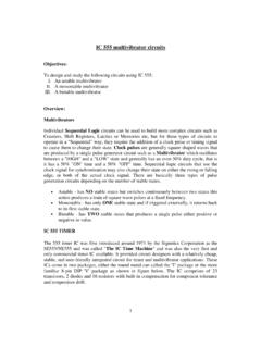
2 Theory: A simple pendulum consists of a small body called a bob (usually a sphere) attached to the end of a string the length of which is great compared with the dimensions of the bob and the mass of which is negligible in comparison with that of the bob. Under these conditions the mass of the bob may be regarded as concentrated at its center of gravity, and the length of the pendulum is the distance of this point from the axis of suspension. When the dimensions of the suspended body are not negligible in comparison with the distance from the axis of suspension to the center of gravity, the pendulum is called a compound, or physical, pendulum. A rigid body mounted upon a horizontal axis so as to vibrate under the force of gravity is a compound pendulum. In a body of irregular shape is pivoted about a horizontal frictionless axis through P and is displaced from its equilibrium position by an angle . In the equilibrium position the center of gravity G of the body is vertically below P.
3 The distance GP is l and the mass of the body is m. The restoring torque for an angular displacement is = - mg l sin (1) P. For small amplitudes ( 0), .. l , (2) L. where I is the moment of inertia of the body through the axis P. Eq. (2) represents a simple harmonic motion and hence the time G. period of oscillation is given by .. 2 .. (3) O. Now , where IG is the moment of inertia of the body about an axis parallel with axis of oscillation and passing through the center of gravity G. IG = mK2 (4) Fig. 1. where K is the radius of gyration about the axis passing through G. Thus, 1.. 2 .. 2 .. (5). The time period of a simple pendulum of length L, is given by . 2 .. (6). Comparing with Eq. (5) we get .. (7). This is the length of equivalent simple pendulum . If all the mass of the body were concentrated ! . at a point O (See ) such that , we would have a simple pendulum with the same time period. The point O is called the Centre of Oscillation'. Now from Eq.
4 (7).. " 0 ..(8). a quadratic equation in l. Equation 6 has two roots l1 and l2 such that $ . and $ " (9). Thus both $ and are positive. This means that on one side of there are two positions of the centre of suspension about which the time periods are the same. Similarly, there will be a pair of positions of the centre of suspension on the other side of the about which the time periods will be the same. Thus there are four positions of the centers of suspension, two on either side of the , about which the time periods of the pendulum would be the same. The distance between two such positions of the centers of suspension, asymmetrically located on either side of , is the length L of the simple equivalent pendulum. Thus, if the body was supported on a parallel axis through the point O (see Fig. 1), it would oscillate with the same time period T as when supported at P. Now it is evident that on either side of G, there are infinite numbers of such pair of points satisfying Eq.
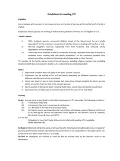
5 (9). If the body is supported by an axis through G, the time period of oscillation would be infinite. From any other axis in the body the time period is given by Eq. (5). From Eq.(6) and (9), the value of g and K are given by . 4 ) (10). " *$ (11). By determining L, $ and graphically for a particular value of T, the acceleration due to gravity g at that place and the radius of gyration K of the compound pendulum can be determined. 2. Description: The bar pendulum consists of a metallic bar of about one meter long. A series of circular holes each of approximately 5 mm in diameter are made along the length of the bar. The bar is suspended from a horizontal knife-edge passing through any of the holes (Fig. 2). The knife- edge, in turn, is fixed in a platform provided with the screws. By adjusting the rear screw the platform can be made horizontal. Fig. 2 Fig. 3. Procedure: (i) Suspend the bar using the knife edge of the hook through a hole nearest to one end of the bar.
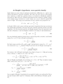
6 With the bar at rest, focus a telescope so that the vertical cross-wire of the telescope is coincident with the vertical mark on the bar. (ii) Allow the bar to oscillate in a vertical plane with small amplitude (within 40 of arc). (iii) Note the time for 20 oscillations by a precision stop-watch by observing the transits of the vertical line on the bar through the telescope. Make this observation three times and find the mean time t for 20 oscillations. Determine the time period T. (iv) Measure the distance d of the axis of the suspension, the hole from one of the edges of the bar by a meter scale. (v) Repeat operation (i) to (iv) for the other holes till of the bar is approached where the time period becomes very large. 3. (vi) Invert the bar and repeat operations (i) to (v) for each hole starting from the extreme top. (vii) Draw a graph with the distance d of the holes as abscissa and the time period T as ordinate. The nature of graph will be as shown in Fig.
7 3. Draw the horizontal line ABCDE parallel to the X-axis. Here A, B, D and E represent the point of intersections of the line with the curves. Note that the curves are symmetrical about a vertical line which meets the X-axis at the point G, which gives the position of the of the bar. This vertical line intersects with the line ABCDE at C. Determine the length AD and BE and find the +, -.. length L of the equivalent simple pendulum from /.. Find also the time period T corresponding to the line ABCDE and then compute the value of g. Draw several horizontal lines parallel to X-axis and adopting the above procedure find the value of g for each horizontal line. Calculate the mean value of g. Alternatively, for each horizontal line obtain the values of L and T and draw a graph with T2 as abscissa and L as ordinate. The graph would be a straight line. By taking a convenient point on the graph, g may be calculated. Similarly, to calculate the value of K, determine the length AC, BC or CD, CE of the line ABCDE and compute 12 B2 or 24 25.
8 Repeat the procedure for each horizontal line. Find the mean of all K. Observations: Table 1-Data for the T versus d graph Serial no of Distance d of Time for 20 Mean time t for Time period holes from one the hole from oscillations (sec) 20 oscillations T = t/20 (sec). end one end (cm) (sec). One 1 .. side of .. 2 .. 3 .. Other 1 .. side of .. 2 .. 3 .. 4. TABLE 2- The value of 6 and K from T vs. d graph . 4 . No. of obs. T Mean ' K Mean K'. (cm) (sec) (cm/sec2) (cm) (cm). (cm/sec2). 1. ABCDE (AD+BE)/2 .. 12 B2. or 24 25. 2.. 3.. Computation of proportional error: We have from Eq. (10). 7 / / 9. 4 : 7 9 . (12). ;. Since L = Lx/2 (Lx= AD+BE) and T = t/20, therefore, we can calculate the maximum proportional error in the measurement of g as follows < . = / > =2 >. < < .. (13). /. ? @ = the value of the smallest division of the meter scale ?A = the value of the smallest division of the stop-watch Precautions and Discussions: (i) Ensure that the pendulum oscillates in a vertical plane and that there is no rotational motion of the pendulum.
9 (ii) The amplitude of oscillation should remain within 40 of arc. (iii) Use a precision stop-watch and note the time accurately as far as possible. (iv) Make sure that there is no air current in the vicinity of the pendulum. References: 1. Fundamentals of PHYSICS : Resnick & Halliday 2. Practical PHYSICS : Shukla, Anchal Srivatsava, New Age International (P) Ltd, New Delhi 3. Eric J. Irons, American Journal of PHYSICS , Vol. 15, Issue 5, (1947). 5. Moment of Inertia of different bodies and parallel axis theorem Aim: 1) Study moment of inertia of different bodies and 2) prove the parallel axis theorem (Steiner's theorem). Objectives of the experiment (Part 1). Determining the moments of inertia of rotationally symmetric bodies from their period of oscillation on a torsion axle. Comparing the periods of oscillation of two bodies having different masses, but the same moment of inertia. Comparing the periods of oscillation of hollow bodies and solid bodies having the same mass and the same dimensions.
10 Comparing the periods of oscillation of two bodies having the same mass and the same body shape, but different dimensions. Thoery: The moment of inertia is a measure of the resistance of a body against a change of its rotational motion and it depends on the distribution of its mass relative to the axis of rotation. For a calculation of the moment of inertia J, the body is subdivided into sufficiently small mass elements mi with distances ri from the axis of rotation and a sum is taken over all mass elements: . (1). For bodies with a continuous mass distribution, the sum can be converted into an integral. If, in addition, the mass distribution is homogeneous, the integral reads . (2). The calculation of the integral is simplified when rotationally symmetric bodies are considered which rotate around their axis of symmetry. The simplest case is that of a hollow cylinder with radius R. As all mass elements have the distance R from the axis of rotation, the moment of inertia of the hollow cylinder is.