Transcription of IC 555 multivibrator circuits - NISER
1 1 IC 555 multivibrator circuits Objectives: To design and study the following circuits using IC 555: I. An astable multivibrator II. A monostable multivibrator III. A bistable multivibrator Overview: Multivibrators Individual Sequential Logic circuits can be used to build more complex circuits such as Counters, Shift Registers, Latches or Memories etc, but for these types of circuits to operate in a "Sequential" way, they require the addition of a clock pulse or timing signal to cause them to change their state. Clock pulses are generally square shaped waves that are produced by a single pulse generator circuit such as a multivibrator which oscillates between a "HIGH" and a "LOW" state and generally has an even 50% duty cycle, that is it has a 50% "ON" time and a 50% "OFF" time.
2 Sequential logic circuits that use the clock signal for synchronization may also change their state on either the rising or falling edge, or both of the actual clock signal. There are basically three types of pulse generation circuits depending on the number of stable states, Astable - has NO stable states but switches continuously between two states this action produces a train of square wave pulses at a fixed frequency. Monostable - has only ONE stable state and if triggered externally, it returns back to its first stable state. Bistable - has TWO stable states that produces a single pulse either positive or negative in value.
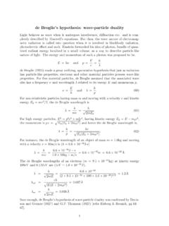
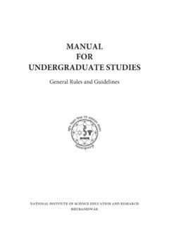
3 IC 555 TIMER The 555 timer IC was first introduced around 1971 by the Signetics Corporation as the SE555/NE555 and was called "The IC Time Machine" and was also the very first and only commercial timer IC available. It provided circuit designers with a relatively cheap, stable, and user-friendly integrated circuit for timer and multivibrator applications. These ICs come in two packages, either the round metal-can called the 'T' package or the more familiar 8-pin DIP 'V' package as shown in figure below. The IC comprises of 23 transistors, 2 diodes and 16 resistors with built-in compensation for component tolerance and temperature drift.
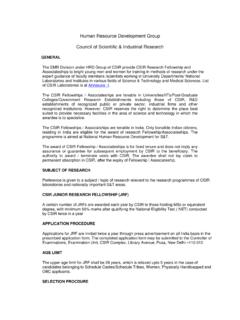
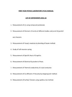
4 2 IC 555 in 8-pin DIP package Functional block diagram of IC 555 The pin connections are as follows: 1. Ground. 2. Trigger input. 3. Output. 4. Reset input. 5. Control voltage. 6. Threshold input. 7. Discharge. 8. +VCC. +5 to +15 volts in normal use. Pin1: Ground. All voltages are measured with respect to this terminal. Pin2: Trigger. The output of the timer depends on the amplitude of the external trigger pulse applied to this pin. When a negative going pulse of amplitude greater than 1/3 VCC is applied to this pin, the output of the timer high. The output remains high as long as the trigger terminal is held at a low voltage.
5 Pin3: Output. The output of the timer is measured here with respect to ground. There are two ways by which a load can be connected to the output terminal: either between pin 3 and ground or between pin3 and supply voltage +VCC. When the output is low the load current flows through the load connected between pin3 and +VCC into the output terminal and is called sink current. The current through the grounded load is zero when the output is low. For this reason the load connected between pin 3 and +VCC is called the normally on load (we will use this for our circuit ) and that connected between pin 3 and ground is called normally off- load .
6 On the other hand, when the output is high the current through the load connected between pin 3 and +VCC is zero. The output terminal supplies current 3 to the normally off load . This current is called source current. The maximum value of sink or source current is 200mA. Pin4: Reset. The 555 timer can be reset (disabled) by applying a negative pulse to this pin. When the reset function is not in use, the reset terminal should be connected to +VCC to avoid any possibility of false triggering. Pin5: Control Voltage. An external voltage applied to this terminal changes the threshold as well as trigger voltage.
7 Thus by imposing a voltage on this pin or by connecting a pot between this pin and ground, the pulse width of the output waveform can be varied. When not used, the control pin should be bypassed to ground with a F Capacitor to prevent any noise problems. Pin6: Threshold. When the voltage at this pin is greater than or equal to the threshold voltage 2/3 VCC, the output of the timer low. Pin7: Discharge. This pin is connected internally to the collector of transistor Q. When the output is high Q is OFF and acts as an open circuit to external capacitor C connected across it.
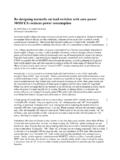
8 On the other hand, when the output is low, Q is saturated and acts as a short circuit , shorting out the external capacitor C to ground. Pin8: +VCC. The supply voltage of +5V to + 18V is applied to this pin with respect to ground. OPERATION: The functional block diagram shows that the device consists of two comparators, three resistors and a flip-flop. A comparator is an OPAMP that compares an input voltage and indicates whether an input is higher or lower than a reference voltage by swinging into saturation in both the direction.
9 The operation of the 555 timer revolves around the three resistors that form a voltage divider across the power supply to develop the reference voltage, and the two comparators connected to this voltage divider. The IC is quiescent so long as the trigger input (pin 2) remains at +VCC and the threshold input (pin 6) is at ground. Assume the reset input (pin 4) is also at +VCC and therefore inactive, and that the control voltage input (pin 5) is unconnected. The three resistors in the voltage divider all have the same value (5K in the bipolar version of this IC and hence the name 555), so the trigger and threshold comparator reference voltages are 1/3 and 2/3 of the supply voltage, respectively.
10 The control voltage input at pin 5 can directly affect this relationship, although most of the time this pin is unused. The internal flip-flop changes state when the trigger input at pin 2 is pulled down below +VCC/3. When this occurs, the output (pin 3) changes state to +VCC and the discharge transistor (pin 7) is turned off. The trigger input can now return to +VCC; it will not affect the state of the IC. 4 However, if the threshold input (pin 6) is now raised above +(2/3)VCC, the output will return to ground and the discharge transistor will be turned on again.