Transcription of Flare Identification Chart - fedhillusa.com
1 Tube + or - .0073/16 .272 1/4 .352 5/16 .418 3/8 .493 1/2 .632 Tube + or - .0103/16 .270 1/4 .350 5/16 .415 + or - .0153/8 .475 1/2 .645 Double/SAE 45 Degree FlareDIN/ISO Bubble FlareAN/JIC 37 Degree Single Flare90 DEG+ or - 445 DEGTool MarksAcceptable Less ThanTube RequiredNo Nicks AllowedDebur Die Blocks If NeededRadius RequiredNo Nicks AllowedDebur Die Blocks If MarksAcceptable Flare Less ThanTube + or - . RequiredNo Nicks AllowedDebur Die Blocks If NeededFlare Less ThanTube MarksAcceptable 115 DEG+ or - that the Flare is the correct profile for the components involvedAutomotive fittings are always a 45 deg.
2 Double or DIN flareNever use a single 45 degree Flare with automotive nuts and fittingsA 37 degree single Flare is acceptable for use in AN/JIC nuts and fittings with Cunifer seamless tubingCommon CrossthreadsNever interchange a fully threaded nut with a nut with non-threaded leadNever interchange a nut with anon-threaded lead with a fully threadednutAlways check carefully for diameter and thread pitch Flare Identification Chart195 Federal Hill Road Oxford, MA 01540 Phone: 508-987-2660 Fax: 508-987-2661 10mm x Asian nut with SAE/double Flare10mm x metric nut with DIN/ISO flare3/8 x 24 UNF British Girling nut with old style bubble flare3/8 x 24 UNF American nutwith SAE/double flareNote the non-threaded lead portion on the nuts belowThe 3/8 x 24 UNF American nut will thread very easily and loosely into a 10mm x thread fitting but willhopefully strip the threads when you tighten it downYou can start the 10mm x thread nut in a 3/8 x 24 UNF thread fitting butit will immediatly
3 Begin stripping the threads74 DEG + or - 2 Cunifer Brake Line195 Federal Hill Road Oxford, MA 01540 Phone: 508-987-2660 Fax: 508-987-2661 Stock SizesTheoretical Bursting PressureRecommended Max. Working Pressure at 5 to 1 safety factor with appropriate x Wall (psi) (psi)SAE Range3/16 x 17,0003,2001/4 x 12,4502,3005/16 x 9,4501,8003/8 x 7,9601,4501/2 x 5,8501,050 Metric x ,0003,2006mm x ,0002,4008mm x 9,4501,75010mm x 7,4001,400To ensure a long and trouble-free service life from Cunifer Brake Lines you must fit it properly, usingaccepted engineering practice.
4 The following simple suggestions are offered as a guide to successful other brake line compares for STRENGTH, RELIABILITY and EASE of installation. Installed by high performance manufacturers such as Aston Martin, Porsche and Audi, Cunifer brake lines maintain full strength for the life of the unique properties allow it to be snaked into positions that are impossible to do with steel brake about our 007 flaring tool. Press perfect flares in seconds, with fast cam and lever action. Precision made punch and smooth bore die blocks grip and form Flare without damaging the tubing.
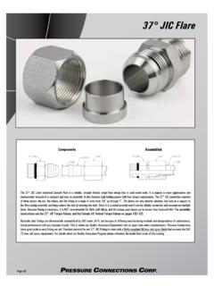
5 Making aircraft quality flares for SAE 45 degree double (inverted) on American or metric size tubing. Din on metric High Performance Alloy Brake Line s composition conforms to SAE J1650 standard for seamless copper-nickel 90-10 tubing for use in hydraulic brake pressure lines. Its dimensions, tensile strength, proof pressure, formability and internal cleanliness conform to international brake tubing specifications including SAE J1650, BS 2871, ASTM A254, SMMT C58 and DIN tubing can be used for original equipment, modi-fications or replacements on all types of brake, fuel line and hydraulic systems.
6 It should be used in appropriate sizes, with appropriate standard fittings and only up to recommended working pressure, as indicated by the Chart InstructionsCutting to LengthDetermine the length of the brake tube required, using stiff wire, solder, tape measure or the old brake lines as a pattern. Cut to the required length using a tube cutter. Do not distort the tube by over-tightening it in the cutter. File the ends to ensure it s square and remove the burrs from the inside and outside edges. Blow filings out of the the NutIf not reusing the original nut, be sure new nuts match exactly with diameter, thread pitch, length, non-threaded lead, etc.
7 Install nut before the EndsThe appropriate single, bubble or double Flare can be formed, using a good quality flaring tool such as the 007 flaring tool. Serrated grips should not be used. Ensure that the dies grip the tube securely without deforming the tube section or denting its surface. Check that the Flare is of the correct profile for the unit and component involved and that it has been formed symmetricallyon the tube the TubingBend the nutted and flared tube carefully to shape, so that it will fit easily into position.
8 Bends should be smooth and have as large a radius as possible. For tight bends on the larger sizes, a rolling die bending tool should be used. A minimum bend radius of three times the tube diameter is recommended. Tubing should not be kinked or strained into position. It should emerge cleanly from the nut without bearing against it. Lubricate the threads and the bearing surface of the Flare to ensure that it and the nut will seat properly and the nut can be tightened without twisting the tube. Do not over tighten the TorqueAs a general rule from finger tight, continue tightening the nut until you feel it draw down tight, then tighten approximately 1/6 turn more.
9 Do not over SupportAll brake tubes should be supported at regular intervals along their length, using steel or plastic clips, each attached firmly to the body or chassis of the vehicle. When tube follows axle casings orsuspension arms, which can induce vibration of the tube, it is essential to secure tightly. Tie wraps work well to secure to rear axle housing. Clips should be spaced at intervals of approximately 12 to 13 inches but no farther apart than those used for steel tubing.