Transcription of Fluidized Bed Introduction - Engineering School Class Web ...
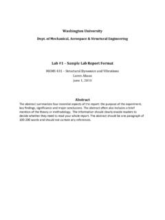
1 Introduction TO Fluidized BEDS chemical REACTION Engineering LABORATORY Outline/Contents Introduction . Fluidization Flow Regimes. Overall Gas (Voidage) and solids Hold-up. Radial and Axial Solids Hold-Up Profiles. Radial and Axial voidage distribution. Gas and Solid Mixing. Scale-Up. Reactor Modeling. chemical REACTION Engineering LABORATORY Fluidized Bed Reactor Components chemical REACTION Engineering LABORATORY The material Fluidized is a solid (catalyst). The fluidizing medium is either a gas or a liquid.
2 Gas distributor Inlet to cyclone Advantages Disadvantages It has the ability to process large volumes of fluid. Excellent gas-solid contacting. Heat and mass transfer rates between gas and particles are high when compared with other modes of contacting. No hot spot even with highly exothermic reaction. Ease of solids handling. chemical REACTION Engineering LABORATORY Broad or even bimodal residence time distribution of the gas due to dispersion and bypass in the form of bubbles.
3 Broad residence time distribution of solids due to intense solids mixing. Erosion of internals. Attrition of catalyst particles. Difficult Scale-up due to complex hydrodynamics. Industrial Applications of Fluidized Bed Reactor Acrylonitrile by the Sohio Process. Fischer-Tropsch Synthesis. Phthalic anhydride synthesis. Methanol to gasoline and olefin processes. Cracking of Hydrocarbons (Fluid Catalytic Cracking, etc). Coal combustion. Coal gasification Cement clinker production. Titanium dioxide production.
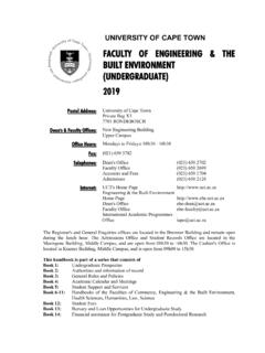
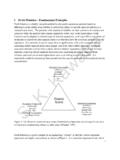
4 Calcination of AL(OH)3. Granulation drying of yeast. Heat exchange Absorption Nuclear energy (Uranium processing, nuclear fuel fabrication, reprocessing of fuel and waste disposal). chemical REACTION Engineering LABORATORY Yang 2003 Fluidization Flow Regimes chemical REACTION Engineering LABORATORY Geldart's Classification of Powders Group A (Aeratable) :- ( , Ammoxidation of propylene) small mean particle size and/or low particle density (<~ g/cm3), gas bubbles appear at minimum bubbling velocity (Umb).
5 Group B (Sand-Like) :- ( ,Starch) particle size 40 m to 500 m and density to 4 g/cm3, gas bubbles appear at the minimum fluidization velocity (Umb). Group C (Cohesive) :- very fine particle, particle size < 30 m, difficult to fluidize because inter-particle forces are relatively large, compared to those resulting from the action of gas. Group D (Spoutable) :- ( , Roasting coffee beans) large particle, stable spouted beds can be easily formed in this group of powders. 3kg^Kunii and Levenspiel (1991) Diagram of the Geldart classification of particles, Geldart (1973 ).
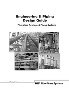
6 Flow Regimes in Fluidized Beds chemical REACTION Engineering LABORATORY J. Ruud van Ommen, 2003 Minimum Fluidization Velocity mf This equation can be used to calculate the minimum fluidization velocity U if the void fraction mf at incipient fluidization is known. Experimentally, the most common method of measurement requires that pressure drop across the bed be recorded as the superficial velocity is increased stepwise through Umf and beyond, Umf is then taken at the intersection of the straight lines corresponding to the fixed bed and Fluidized bed portions of the graph obtained when is plotted against U on log-log coordinates.
7 BedP Kunii and Levenspiel (1991) Bubbling Fluidization This type of fluidization has been called aggregative fluidization , and under these conditions, the bed appears to be divided into two phases, the bubble phase and the emulsion phase. The bubbles appear to be very similar to gas bubbles formed in a liquid and they behave in a similar manner. The bubbles coalesce as they rise through the bed. chemical REACTION Engineering LABORATORY High solid hold-ups (typically 25-35 % by volume). Limited axial mixing of gas.
8 Suitable for exothermic and fast reactions. Good gas-solid contact and hence, favors reactant conversion. high gas flow-rates operation and good for isothermal operation. Favorable bed to surface heat transfer. chemical REACTION Engineering LABORATORY Turbulent Fluidization Turbulent regime has the following features:- Canada et al. 1978 Some commercial processes in turbulent fluidization chemical REACTION Engineering LABORATORY Process Particle classification Typical gas velocity (m/s) FCC regenerators Group A Acrylonitrile Group A ~ Maleic anhydride Group A ~ Phthalic anhydride Group A ~ Ethylene dichloride Group A ~ Roasting of zinc sulfide Group A ~ Bi et al.
9 2000 Fast Fluidized Bed The fast fluidization occurs as a result of continuing increasing in operating velocity beyond that required at turbulent fluidization, a critical velocity, commonly called the transport velocity (Utr), will be reached where a significant particle entrainment occurs. The CFB has significant industrial applications because of its efficiency, operational flexibility, and overall profitability (Berruti et al., 1995). chemical REACTION Engineering LABORATORY Transition between Fluidization Regimes.
10 Grace (1986a) summarized the effects of particles properties and operating conditions on fluidization behavior and prepared a flow regime diagram. The flow regime diagram was further modified by Kunii and Levenspiel (1997). For given particles and operating velocity, the gas-solid contact pattern can be determined using this diagram. Likewise, for a given flow regime, this diagram could provide available combinations of particle properties and gas velocity. Yang 2003 Fluidization diagram avsGsUU Solid hold-up Yerushalmi and Cankurt, 1970 Methods for Regime Transition Identification Several measurement methods have been utilized to determine the transition from bubbling or slugging to turbulent fluidization which can be classified into three groups:- Visual Observation.