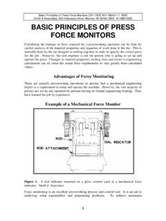
Transcription of Forming Flanges & Process Limitations - Smith & …
1 Forming Flanges and Process Limitations C041 REV June 23, 2005 Smith & Associates, 530 Hollywood Drive, Monroe, michigan 48162-2943 1993, 2001 Forming Flanges AND Process Limitations Flanges on metal parts fall into three basic types. The simplest is the straight flange that is a straight bend. Concave Flanges are termed stretch Flanges because the metal formed into the flange stretches. Convex Flanges are shrink Flanges , since the metal is compressed or shrunk. In addition, there are combinations of these types of Flanges that occur in a single operation. Some Limiting Factors In flanging There are factors that place limits on the flanging Process .
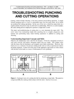
2 These include: 1. The severity of deformation accomplished before fractures occur. 2. The amount of wrinkling or puckering that is permissible on a compression flange . 3. Press energy or force available for flanging large areas with conventional wipe Flanges high in the press stroke. flange Types Figure 1 illustrates a number of different Flanges . The straight flange is the most common type. The problems associated with straight Flanges are springback and scoring. Close tolerance bends should not be specified unless necessary to enhance the appearance or function of the part.
3 A variation in elastic recovery or springback is a problem. This results from variations in material properties Forming stretch Flanges involves stretching the metal during the bending operation. The greatest amount of stretch occurs at the edge of the flange , and is essentially zero at the bend radius. The metal in a shrink flange compresses causing it to shorten in length. The amount of shrinkage is greatest at the edge of the flange and diminishes to zero at the bend radius. Irregular or curved Flanges tend to have less springback problems than straight Flanges .
4 A reverse flange is a combination of a stretch and shrink flange . Another combination flange is the joggled flange . While the majority of the flange is straight, the corners are stretch and shrink Flanges respectively. A flanged hole is a type of stretch flange . Some flanged hole applications are locating bosses, holes for tapped threads, openings for heat transfer tubes, and non-chafing passages for wires. Flanging an opening in a stamping can greatly increase part rigidity. 1 Forming Flanges and Process Limitations C041 REV June 23, 2005 Smith & Associates, 530 Hollywood Drive, Monroe, michigan 48162-2943 1993, 2001 Various flange Types Figure 1.
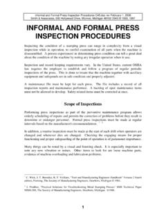
5 Examples of types of Flanges : a straight bend or flange (A). A stretch flange (B). In shrink Flanges the metal is compressed (C). A reverse flange is a combination of a stretch and shrink flange (D). A joggled flange (E). A Flanged hole is a type of stretch flange (F). Smith & Associates 2 Forming Flanges and Process Limitations C041 REV June 23, 2005 Smith & Associates, 530 Hollywood Drive, Monroe, michigan 48162-2943 1993, 2001 Stretch Flanging Problems Edge splitting can be a problem when stretch flanging as illustrated in Figure 22. The likelihood of splitting depends on the material properties, and the edge condition resulting from shearing or trimming.
6 Tensile stress can reduced by shorter flange lengths or by providing notches or scallops. Notches will reduce the flange strength. Stretch Flanging Problems Figure 2. Edge splitting can be a problem (A) when stretch flanging. Reduce the tensile stress by providing notches or scallops (B). Smith & Associates Minimum Bend Radii The minimum bend radii vary depending on the type of metal. Most annealed metals can be bent to a radius equal to the thickness, although some softer metals can be bent to an inside radius one-half metal thickness. Short bend radius lengths reduce the minimum bend radius.
7 This is not a practical consideration if the minimum bend radius length is eight or more times the metal thickness. The rolling direction in sheet or strip metal limits the minimum bend radius. An angle of 90 degrees between the bend axis and the direction of rolling allows most metals to bend to the smallest possible radii. 3 Forming Flanges and Process Limitations C041 REV June 23, 2005 Smith & Associates, 530 Hollywood Drive, Monroe, michigan 48162-2943 1993, 2001 A simple general equation expresses the strain at the edge of the stretch flange , where most failures begin: R2 ex = - 1 (equation 1) R1 Where.
8 Ex = strain at flange edge R1 = flange edge radius before Forming R2 = flange edge radius after Forming Circle Grid Analysis (CGA) is an excellent method for determining the actual amount of strain at a flanged edge. Expanding a drilled, deburred hole with a lubricated conical punch to determine the Forming limit may perform a simple comparative test for materials to be flanged. Edge conditions such as burrs and rough fractured edges reduce stretch flange formability. Such edge conditions result in excessive cold working of the metal.
9 Bend Allowances For close work, the exact length of metal required to make a bend requires trial and error. The assumed neutral axis varies depending upon the bending method used, the location in the bend, and the type of stock bent. Direction of grain in a steel strip relative to the bend also has a slight effect on the length of metal required to make a bend. Bending with the grain allows the metal to stretch more easily than bending against the grain; however, this results in a weaker stamping. Bend allowance depends more upon the physical properties of the material such as tensile strength, yield strength, and ductility than on the actual metal composition.
10 Empirical Rules An important factor that determines the neutral axis is how the bend is accomplished. Less metal is required for a bend made by a tightly wiped flange than for an air bend on a press brake. Wiping the flange tends to stretch the metal. The exact bend allowance is the arc length of the true neutral axis of the bend. Above the neutral axis, metal stretches below it, metal is compressed. The problem is that neutral axis can only be approximated. 4 Forming Flanges and Process Limitations C041 REV June 23, 2005 Smith & Associates, 530 Hollywood Drive, Monroe, michigan 48162-2943 1993, 2001 Many manufacturers calculate neutral axis as 33% of stock thickness from the inside radius of the bend for inside radii of less than twice stock thickness.