Transcription of FOUNDATIONS FOR WIND TURBINES
1 FOUNDATIONS FOR WIND TURBINES ENGR 340 Fall 2011 Jeramy C. Ashlock Assistant Professor, CCEE Vern Schaefer Professor, CCEE OUTLINE Topics Lecture # Design requirements, Foundation types 1 Overview of geotechnical engineering soil mechanics Site investigations In-situ tests Laboratory tests 1 & 2 FOUNDATIONS for wind TURBINES , Design example 2 2 TURBINE FOUNDATION LOADS Vertical, shear forces and significant overturning moments are transmitted to foundation by tower Must be resisted within tolerances for foundation settlement and tilt Manufacturers typically specify horizontal and rotational foundation stiffness criteria Loading direction changes with wind direction and nacelle orientation Circular foundation shape is therefore optimal, but straight-sided ( octagonal, hexagonal) is easier to construct Anchors can be used to add rotational strength 3 FOUNDATION CONTACT STRESS UNDER ECCENTRIC/MOMENT LOADS To prevent loss of contact and uplift, the foundation is typically designed such that the eccentricity e of the resultant is e < B/6.
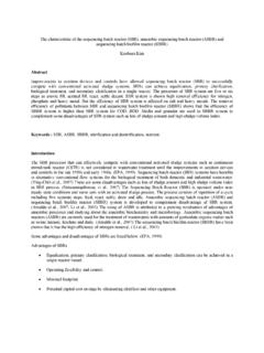
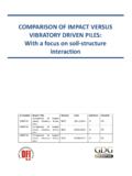
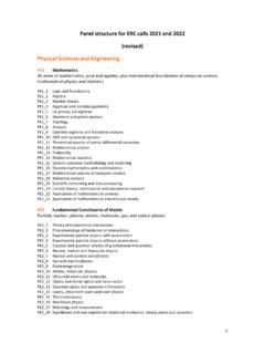
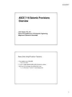
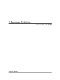
2 In other words, M<PB/6. 4 OFFSHORE FOUNDATION OPTIONS Source: Malhothra, 2011 5 OFFSHORE FOUNDATIONS Photos: NREL 6 TYPICAL TURBINE FOUNDATION OPTIONS On rock or competent soil : Shallow concrete inverted tee mat FOUNDATIONS ($) On weak or soft soils (bearing capacity or stiffness too low, settlements too high): Rammed Aggregate Piers or VibroPiers under footings or mats ($$) soil improvement such as deep soil mixing, compaction, over-excavation & replacement with compacted lifts of aggregate ($$$) Deep FOUNDATIONS ; piles, drilled shafts ($$$$) Concrete-filled corrugated pipe with post-tensioned anchor bolts (proprietary design; $$?) 7 SHALLOW/SLAB FOUNDATION VARIANTS 8 PILED FOUNDATION VARIANTS 9 PILED FOUNDATION VARIANTS 10 OCTAGONAL SHALLOW MAT FOUNDATIONS Source: GeoPier / 11 OCTAGONAL SHALLOW MAT FOUNDATIONS Typical dimensions: Footing width: 50-65 ft avg. depth: 4-6 ft Pedestal diameter: 18-20 ft height: 8-9 ft 50-65 ft 4-6ft 18-20 ft 8-9 ft 12 RAMMED AGGREGATE PIERS (RAPs) UNDER FOOTINGS OR MATS Source: GeoPier / 13 RAPs UNDER FOOTINGS OR MATS RAPs are used for Decreased settlements Improved bearing capacity in weak or compressible soils Increased rotational stiffness Uplift resistance Alternative solutions for uplift resistance: helical anchors or helical piles 14 ANCHORS FOR UPLIFT RESISTANCE 15 P&H TENSIONLESS FOUNDATION DESIGN Proprietary design of Patrick & Henderson, Inc.
3 Concentric corrugated metal pipes filled with concrete that is compressed by post-tensioned rods 16 For more info, see Patent # 5586417 17 FOUNDATIONS MUST BE DESIGNED FOR THE SITE CONDITIONS OF EACH PROJECT, NOT JUST SELECTED Using site-specific design loads and carrying out site-specific wind turbine designs is somewhat in contrast with the current trend within the wind turbine industry. In order to keep down manufacturing costs, the current trend is not to site-optimise wind TURBINES , but rather to produce a selection of standard wind TURBINES . The task is then to choose a standard wind turbine from this selection and verify that it is suitable for a given location. The tower and the foundation may still be site-optimised if desirable, and site-specific loads will be required for this purpose. The foundation design will always have to be site-specific in that it needs to be designed for the prevailing local soil conditions.
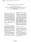
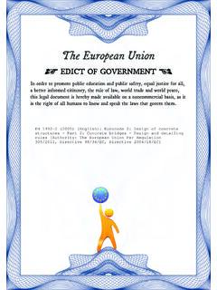
4 Guidelines for Design of Wind TURBINES , 2nd ed. DNV/Ris 18 FOUNDATIONS MUST BE DESIGNED FOR THE SITE CONDITIONS OF EACH PROJECT, NOT JUST SELECTED Foundation designs are integrated into the type certification for some TURBINES . Where this is the case, the foundation design must be evaluated for the external conditions for which it is intended. Poor geotechnical investigation and foundation design have led to delays and cost overruns at European wind farms (Gerdes et al. 2006). Structural Integrity of Offshore TURBINES Oversight of Design, Fabrication and Installation, TRB Special Report 305, 2011 19 DESIGN STEPS/CHECKS FOR SHALLOW FOUNDATIONS embedment below frost depth capacity : Elastic, Consolidation and Differential against sliding and overturning design of foundation (typ. reinforced concrete) stiffness accounting for modulus degradation due to cyclic loading analysis for avoiding resonance of soil -foundation- structure system and erosion (for offshore FOUNDATIONS ) 20 BEARING CAPACITY: ECCENTRICITY OF LOAD - Design loads V, H act at the foundation base - Eccentricity e = M/V - H is reduced if a torque Mz acts about vertical axis (see DNV/Ris Guidelines) 21 BEARING CAPACITY: EFFECTIVE AREA FOR ECCENTRIC LOAD Reduced effective foundation area Aeff =beff leff is defined such that the eccentric vertical load is at the center of the effective area: 22 2effeffbbelb BEARING CAPACITY: EFFECTIVE AREA FOR DOUBLY ECCENTRIC LOAD - For square FOUNDATIONS , a doubly eccentric load further reduces the effective area.
5 - Since direction of eccentricity varies with nacelle orientation, a circular foundation plan is the most efficient 23 2effeffblbe BEARING CAPACITY: EFFECTIVE AREA FOR ECCENTRIC LOAD ON OCTAGONAL/CIRCULAR FOUNDATIONS - Octagonal foundation is more practical for construction - Ellipse is used for reduced area: 24 21222c o s2 M a jo r a x is : 2112M in o r a x is : 2 ()e ffeeeRRAe ReblRRbRe BEARING CAPACITY: EFFECTIVE AREA FOR ECCENTRIC LOAD ON OCTAGONAL/CIRCULAR FOUNDATIONS - Ellipse can be replaced by equivalent rectangle for ease of design calculations: 25 T a k e th e n eeffeffeeeffeffebbllllAb BEARING CAPACITY Fully drained (long-term) conditions: Undrained (short-term or rapid loading) conditions in clay: Generally need to apply shape, depth, & inclination factors as well 26 12u ltcqeffqc Nq NbN 0, 0, 1,uqNN u ltucqc Nq SETTLEMENT Total settlement ST = Se + Sc + Ss Se = Elastic settlement (immediate).
6 Most important for sands. Sc = Consolidation settlement; due to squeezing out of water and air from pore space. Most important for clays, small for sands. Can take years to complete. Rate and amount of settlement determined from consolidation theory combined with lab tests. Ss = Secondary settlement; long-term rearrangement of soil structure under constant effective stress. Magnitude depends on mineral types present in soil 27 FS AGAINST SLIDING cb = adhesion between soil and foundation, often taken as 1/2 to 2/3 of the soil s cohesion b = angle of interface friction between soil & base, often taken as 1/2 to 2/3 of For Undrained conditions in clay, u = 0; 28 tan( h o r. resistin g fo rces)1 .5( h o r. d rivin g fo rces)beffbscAVFH 1 .5beffscAFH FS AGAINST OVERTURNING Similar to the case of sliding, we can take the ratio of restoring moments to overturning moments: Loss of contact is usually ensured by keeping e<B/6 29 ( resto rin g m o m en ts)1.
7 5,(o vertu rn in g m o m en ts)sF FACTOR OF SAFETY AGAINST OVERTURNING 30 FS < DRAINAGE Needed to maintain the design bearing capacity as calculated based on the assumed maximum water table elevation Can be provided by using drainage tiles , free-draining backfill, and sloping the finished grade away from foundation to prevent ponding Excessive wetting of clay soils can cause expansion differential settlements Excessive drying of clay soils ( from nearby vegetation) can cause shrinking settlements 31 DYNAMIC analysis : COUPLED soil - structure INTERACTION A complete natural frequency analysis shall be performed for the combined structure consisting of turbine, tower, tripod and piles [and soil ]. For this purpose, the non- linear soil must be linearized. It is to be verified that the lowest frequencies differ from at least 10% of the 1P and 3P rotor frequencies at nominal power. Guidelines for Design of Wind TURBINES , 2nd ed.
8 DNV/Ris 32 DYNAMIC analysis : COUPLED soil - structure INTERACTION The dynamics and relative stiffness of the supporting structural and foundation components, commonly envisaged as a monotower in shallow water (but which could be a vertical axis system, a floating system, etc.), have an interrelationship with the stiffness and rotation frequency and loads of the blades that must be carefully addressed in the design for long-term performance. Structural Integrity of Offshore TURBINES Oversight of Design, Fabrication and Installation, TRB Special Report 305, 2011 33 DYNAMIC FOUNDATION STIFFNESS Dynamic soil - structure Interaction (SSI): dynamic soil response affects response of structure and vice-versa Stiffness of soil is generally nonlinear and frequency dependent, but often simplified in terms of springs and dashpots Stiffness (shear modulus G) and damping ( ) depend nonlinearly on cyclic shear strain c As c increases, G decreases from small-strain value Gmax while increases Design: must use a reduced G based on anticipated shear strain level (typically 10-2 to 10-3 for wind TURBINES ) in dynamic analysis of soil -foundation-turbine system G can then be used to obtain an equivalent elastic Young s modulus E for calculating elastic settlements using the reduced foundation area (see Mayne et al.)
9 2002) Mayne, et al., Subsurface Exploration-Geotechnical Characterization , FHWA Publication NHI-01-031, May 2002. 34 DESIGN OF PILE FOUNDATIONS Ensoft (1996), Computer Program Group User s Manual 35 More complicated than shallow FOUNDATIONS Covered in CE 561 REFERENCES Selected information, images and figures are from Ashlock, , Iowa State University CCEE Dept. Bowles (1982), Foundation analysis and Design, 3rd ed., McGraw-Hill Chang and DiMaggio (2002), Geotechnical Engineering Circular No. 6, Shallow FOUNDATIONS , Federal Highway Administration Office of Bridge Technology Coduto (2001), Foundation Design, Principles and Practices, Prentice Hall Das (2011), Principles of Foundation Engineering, 7th ed., Cengage Learning DNV/Ris (2002), Guidelines for Design of Wind TURBINES , 2nd ed., Denmark. GeoPier Foundation Company Hayward Baker Geotechnical Construction Malhotra, S. (2011), Selection, Design and Construction of Offshore Wind Turbine FOUNDATIONS , Wind TURBINES , Ibrahim Al-Bahadly (Ed.
10 , ISBN: 978-953-307-221-0, InTech, Available from: Mayne, , Christopher, , and DeJong, (2002) Manual on Subsurface Investigations, FHWA Publication No. FHWA NHI-01-031, 294 pp. National Renewable Energy Laboratory (NREL) Pile Driving Contractors Association (PDCA) Reese, Isenhower and Wang (2006), analysis and Design of Shallow and Deep FOUNDATIONS , Wiley Terracon Consulting Engineers and Scientists, Des Moines, IA 36