Transcription of FPK FPS PN02068202 - hydac-na.com
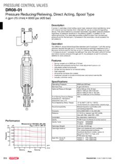
1 AccumulatorsCharging & Gauging UnitsFPK / FPS Operating #02068202 s !#5 2 Charging & Gauging UnitsPN#02068202 s !#5 ACCUMULATORSFPSV ersion 4 FPKV ersion 1valve protection cap(where applicable)Valve seal capO-ringAllen Wrench 6 mm(to be used to crack open M8 handle on FPK Charging is not robustenough to overcome recommended torque)Valve protection cap(where applicable)O-ring (where applicable)Socket HeadCap Screw (M8)Seal ringT-HandleT-HandleCheckValveCap NutCap NutManualBleedValveManualBleedValveFigur e 1 Figure 23 Charging & Gauging UnitsPN#02068202 s !#5 ACCUMULATORSG eneral Warning!Hydraulic accumulators are pressurized vessels and only qualified technicians should perform maintenance.
2 For additional information refer to hydac Operating and Installation Instructions and hydac Maintenance Instructions. Read all instructions thoroughly before before beginning any type of service or Required1. Gas Valve Core Tool. 2. Torque Wrenches. 3. Wrench(es).Intervals Between Checking Gas Precharge PressureThe proper gas precharge pressure should be set after each new installation or repair by following the instructions under the Operating and Installation Instructions below. It should be rechecked at least once during the first week of operation. If there is no loss of gas precharge pressure, it should be rechecked again in 3 to 4 months. Thereafter, it should be checked at least once a year.
3 Recharge accumulator when EffectTo ensure that the recommended gas precharge pressure is maintained, even at relatively low of high operating temperatures, the gas precharge pressure should be adjusted for temperature. The formula below relates the precharge temperature (T0) to the operating temperature (T).FahrenheitP0,T0 = P0,T2 x (T0 + 460) / (T2 + 460)CelsiusP0,T0 = P0,T2 x (T0 + 273) / (T2 + 273)T0 = precharge temperatureT2 = maximum operating temperatureP0,T0 = gas precharge pressure at precharge temperatureP0,T2 = gas precharge pressure at maximum operating temperatureOperating and Installation InstructionPreparationTo check the gas precharge pressure in an accumulator, it must first be isolated from the system shut off, and all hydraulic pressure relieved.
4 hydac gas valve version 4 (see fig. 2) Unscrew the valve protection cap (where applicable) and the valve seal gas valve version 1 (see fig. 2) Unscrew the valve protection cap (where applicable). Slightly loosen the socket head cap screw with a 6 mm Allen wrench (approx. 1/6 turn, see fig. 2).FPS UnitPrior to connecting the charging and gauging unit to an accumulator, turn T-handle counter-clockwise until resistance is felt. Close manual bleed valve by hand tightening. Connect the unit to the accumulator by screwing cap nut onto hydac gas valve version4; hand tighten (see fig. 1).FPK UnitPrior to connecting the charging and gauging unit to an accumulator, close manual bleed valve by hand tightening.
5 Connect the unit to the accumulator by screwing cap nut onto hydac gas valve version 1; hand tighten (see fig. 1).FPK Unit (with adapter FPK/SB)Prior to connecting the charging and gauging unit to an accumulator, take adapter FPK/SB and unscrew the socket head cap screw 3 full turns counter clockwise using the 6 mm Allen wrench. This is done to prevent gas valve damage and leakage upon installation. Screw the adapter FPK/SB onto hydac gas valve version 4, hand tighten. Close manual bleed valve on the FPK unit hand tight. Connect FPK unit to adapter FPK/SB by screwing cap nut onto the adapter; hand & Gauging UnitsPN#02068202 s !#5 ACCUMULATORSC hecking Gas Precharge PressureConnect the appropriate charging and gauging unit to the accumulator following the instructions under Preparation (see page 2).
6 Note: Temperature affects the gas precharge pressure, please refer to Temperature Effect (see page 2).FPS UnitTurn T-handle A clockwise a maximum of 3 full turns from the full counterclockwise position. The gauge needle should indicate the existing gas precharge pressure. If there is no gas precharge pressure indicated or if it is too low or too high, please follow instructions under the appropriate section, either Pressure Release (see below) or Charging (to right). If desired gas precharge pressure registers, please follow the instructions under Removal of Charging and Gauging Unit (see page 5).FPK UnitTurn T-handle counter clockwise a maximum of 3 full turns. The gauge needle should indicate the existing gas precharge pressure.
7 If there is no gas precharge pressure indicated or if it is too low or too high, please follow instructions under the appropriate section, either Pressure Release (see page 3) or Charging (see page 3). If desired gas precharge pressure registers, please follow the instructions under Removal of Charging and Gauging Unit (see page 4).Pressure ReleaseWith the appropriate charging and gauging unit attached as previously described, gas precharge pressure can be released by carefully opening manual bleed valve. Release the gas precharge pressure very slowly until the desired gas precharge pressure is reached (this insures that the gas temperature does not fluctuate greatly, providing and accurate gas precharge pressure).
8 Close the manual bleed valve. Allow the gas precharge pressure to stabilize. (5 to 10 minutes) recheck, adjust if required. Once the desired gas precharge pressure is reached, please follow the instructions under Removal of Charging and Gauging Unit (see page 5).ChargingWarning!Never use oxygen or air - this could cause an explosion! Use dry nitrogen or other recommended gases. hydac recommends the use of a pressure regulator on the commercially available nitrogen bottle to regulate pressure to the charging and gauging unit. Note: Full nitrogen pressure may damage the gauge. Connect the charging hose to a commercially available nitrogen bottle by means of the G4 adapter (other adapters are available, check with factory for type); the adapter connects to the cap screw G1.
9 Connect cap nut of the charging hose to check valve of the charging and gauging unit (see fig. 1). Connect the appropriate charging and gauging unit to the accumulator by following the instructions previously described (see page 2).Initial ChargingWhen charging an accumulator that has no initial gas precharge, allow 20 to 30 minutes for the gas temperature and thus pressure to stabilize. Recheck the gas precharge pressure and adjust if necessary. FPS UnitTurn T-handle clockwise 3 full turns. Proceed to Filling .FPK UnitTurn T-handle counter clockwise 3 full turns. Proceed to Filling .FPK Unit (with adapter FPK/SB)Turn T-handle clockwise 3 full turns. Proceed to Filling .5 Charging & Gauging UnitsPN#02068202 s !
10 #5 ACCUMULATORSP ressure IncreaseWhen charging an accumulator that has an existing gas precharge, allow 5 to 10 minutes for the gas temperature and thus pressure to UnitTurn T-handle clockwise until the gauge needle begins to deflect, then turn it another full turn. Proceed to Filling .FPK UnitTurn T-handle counter clockwise until the gauge needle begins to deflect, then turn it another full turn. Proceed to Filling .FPK Unit (with adapter FPK/SB)Turn T-handle clockwise until the gauge needle begins to deflect, then turn it another full turn. Proceed to Filling .FillingOpen the shut-off valve on the commercially available nitrogen bottle and slowly fill the accumulator with dry nitrogen very slowly until the pressure in the accumulator reaches 100 psi.