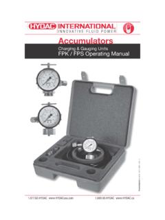
Transcription of Hydac Accessories Master Catalog - …
1 Gauge IsolatorsAccessories Catalog143 Dimensions are for general information only, all critical dimensions should be verified by requesting a certified are in inches/(mm) and (kg.) "(31mm)Hole Requiredin "(33mm) "( ) "(10mm) "( ) "( ) "(88mm) "( )PMT "(26mm)SW 361 7/16" "(80mm)Push to Knob and Turn Clockwise 90for Continuous ReadingCover PlateMax PanelThicknessModel CodeMA 1 . A 1 0 / 5 VGauge Isolator Single StationDesign 1 = Push/Rotating Control KnobConnection A = ThreadedType NumberModification NumberPort Configuration 0 = BSPP Thread (G1/4) Part No. 02057942 5 = 1/4 NPT Thread Part No.
2 02057940 12 = SAE-5 (1/2 -20 UNF) Part No. 02057941 Seals V = Fluoroelastomer Seals (standard)Model Codes containing selections listed in RED italics are non-standard items Minimum quantities will apply Contact Hydac for information and availabilityNot all combinations are availableHydraulic SymbolM Gauge PortPTPushto readDescription Gauge life is extended by using the MA 1 when reading U pressure. When not reading pressure, the gauge is vented to tank to protect the gauge against pressure from the system. There are two ways to operate the MA 1: U Push to read (spring return) Push and rotate clockwise to lock in for continuous pressure readingSpecificationsMountingPanel installation maximum U Connections1/4 NPT, SAE-5, or G1/4 (Ports M, P, T)U kgU Mounting PositionHorizontal or VerticalU Operating FluidMineral OilsU Hydraulic DataOperating PressureP max.
3 5075 psi/350 bar U (T-Port max. 145 psi/10 bar)Temperature Range-4 to 176 F (-20 to 80 C)U DimensionsMA SeriesSingle Gauge IsolatorCourtesy of CMA/Flodyne/Hydradyne Motion Control Hydraulic Pneumatic Electrical Mechanical (800) 426-5480 Gauge IsolatorsAccessories Catalog144 Dimensions are for general information only, all critical dimensions should be verified by requesting a certified are in inches/(mm) and (kg.)Hydraulic Symbol1 2 3T4 5 6 GeneralMounting Method Flange mounting via four 1/4 bolts. It is recommended that the U measuring points with pressures of over 1450 psi (100 bar) be arranged symmetrically.
4 Ports not in use should be lbs. / Mounting PositionOptionalU Fluids General purpose hydraulic oil. For other fluids, U contact Hydac for of Connections6 measuring pointsU 1 tank connectionU Hydraulic DataOperating Pressure Range Max. operating pressure at measuring points 1- 6 U 4500 psi (315 bar)Max. Tank connection pressure 145 psi (10 bar)U Fluid Temperature Range- 5 to 160 F (-20 to 70 C)U Gauge Accuracy Built-in gauge accuracy is of the max. scale value at U 68 F (20 C). The error per additional 50 F (10 C) temperature increase is + and 50 F (10 C) temperature reduction is Values are based on red scale CodeMSL 2 G 2.
5 0 / 315 VMulti-Station Gauge Isolator MSL = Zero Leakage ModelModel 2 = with Built-in Pressure GaugeType and Size of Connection (All Ports) G = 1/4 NPT H = SAE-4 (7/16 -20 UNF) A = BSPP (G1/4)Type NumberModification NumberGauge Indication RangeSizeOperating Pressure Zone (Black Scale)Over Pressure Zone (Red Scale)40 0 - 570 psi (0 - 40 bar)570 - 900 psi (40 - 63 bar)630 - 900 psi (0 - 63 bar)900 -1400 psi (63 - 100 bar)1000 - 1400 psi (0 - 100 bar)1500 - 2300 psi (100 - 160 bar)1800 - 2600 psi (0 - 180 bar)2600 - 3600 psi (180 - 250 bar)3150 - 4500 psi (0 - 315 bar)4500 - 5700 psi (315 - 400 bar)Supplementary Details (omit) = Buna Seals V = Viton SealsModel Codes containing selections listed in RED italics are non-standard items Minimum quantities will apply Contact Hydac for information and availabilityNot all combinations are available0402000100300400506010203 Connections 1-6 formeasuring connectionsAdaptor fortank connectionUse any "0" Position toconnect gauge to tankAdaptor fortank connection123456 TDO NOT REMOVE PLUGS!
6 Make all connections in rearfacing ports shown below. 60 (56mm) (14mm) (109mm) (129mm) (75mm) (7mm) ( ) (11mm) (120mm)90 45 (72mm) (102mm)DimensionsMSL Series Zero Leakage Multi-Station Gauge Isolators with Integral GaugeCourtesy of CMA/Flodyne/Hydradyne Motion Control Hydraulic Pneumatic Electrical Mechanical (800) 426-5480 Gauge IsolatorsAccessories Catalog145 GeneralMounting Method Flange mounting via four 1/4 bolts. It is recommended that U the measuring points with pressures of over 1450 PSI / 100 BAR be arranged symmetrically. Ports not in use should be 4 & MS 5U lbs.
7 / 6 & MS 7U lbs. / PositionOptionalU Fluids General purpose hydraulic oil. For other fluids, U contact the Hydac office for of Connections U MS 4 / MS 6 1 gauge connection (M) 1 tank connection (T) U MS 5 / MS 7 1 gauge connection (M) 1 tank connection (T) 1 leakage connection (L)Hydraulic DataOperating Pressure Range MS 4 / MS 5 / MS 6 / MS 7 U Max. operating pressure range at measuring points 4500 PSI / 315 BAR Max. tank and leakage connection pressure U 145 PSI / 10 BARF luid Temperature Range- 5 to 160 F (-20 to 70 C)U Hydraulic SymbolM = Gauge (measuring) connectioneT = Tank connectionL = Leakage connectionModel CodeMS 4 A 2.
8 1 / 5 VMulti-Station Gauge IsolatorModel 4 = Turn and press to read (6 positions) 5 = Turn to read (5 positions) 6 = Turn and press to read (9 positions) 7 = Turn to read (8 positions)Type and Size of Connections A = Threaded ConnectionsType NumberModification NumberPort Type 5 = NPT Port (1/4 for MS 4 & 5 only) 12 = SAE Port (SAE-4 for MS 4 & 5 only) 0 = BSPP (1/4 for MS 4 & 5 and 1/8 for MS 6 & 7)Seals (omit) = Buna N V = Fluoroelastomer SealsModel Codes containing selections listed in RED italics are non-standard items Minimum quantities will apply Contact Hydac for information and availabilityNot all combinations are availableMS SeriesMulti-Station Gauge Isolators1 3 5 7 9TM2 4 6 8 Type MS 61 3 5 7 LTM2 4 6 8 Type MS 7TM1 2 34 5 6 Type MS 4 Pushto readTM1 2 34 5 LType MS 5 Pushto readCourtesy of CMA/Flodyne/Hydradyne Motion Control Hydraulic Pneumatic Electrical Mechanical (800)
9 426-5480 Gauge IsolatorsAccessories Catalog146 Dimensions are for general information only, all critical dimensions should be verified by requesting a certified are in inches/(mm) and (kg.)DimensionsType MS 4 Type MS 5 (75mm)90 90 45 45 MT215463 (75mm) (125mm) (89mm) (14mm)All Ports are the same thread type-4 SAE, 1/4"NPTF, or G1/4(specified by model code) (6mm) (11mm) (50mm) (7mm) (60mm)Push to read presure,release to connectgauge back to tankTurn to "0" positionto connectgauge back to tank (25mm) typical(spot surface finish)Ports L, M, Tare in this areaPorts 1-6 arein this area (90mm) (60mm)Type MS 6 Type MS 74MT3186275990 90 45 45 (75mm) (75mm)
10 4 MLT31862750 Push to read presure,release to connectgauge back to tankTurn to "0" positionto connectgauge back to tankAll Ports are the same thread typeG1/8 only(specified by model code) (17mm) typical(spot surface finish)Ports L, M, Tare in this areaPorts 1-9 arein this (153mm) (117mm) (28mm) (26mm) (14mm) (6mm) (11mm) (50mm) (7mm) (90mm) (60mm)Courtesy of CMA/Flodyne/Hydradyne Motion Control Hydraulic Pneumatic Electrical Mechanical (800) 426-5480