Transcription of Pressure relief valve, - CMA/Flodyne/Hydradyne
1 1/16 Pressure relief valve, direct operated Type DBDRE 25402 : of contentsContents PageFeatures 1 Ordering code 2, 3 Function, section, symbol 4 technical data 5 General notes 5 Characteristic curves 6 Unit dimensions: Threaded connection 7 Unit dimensions: Cartridge valve 8, 9 Unit dimensions: Subplate mounting 10, 11 Type-tested safety valves type , component series 1X, to Pressure Equipment Directive 97/23/EC (in the following, PED in short) Ordering code 12 Unit dimensions 12 technical data 13 Characteristic curves 13 Safety notes 14 to 16 Features As screw-in cartridge valve For threaded connection For subplate mounting Adjustment types for Pressure adjustment, optional: Sleeve with hexagon and protective cap Rotary knob / hand wheel Lockable rotary knobH5585 Information on available spare parts: 6 to 30 Component series 1 XMaximum operating Pressure 630 bar [9150 psi]Maximum flow 330 l/min [87 US gpm]InhaltTable of contents 1 Features 1 Ordering code 2 3 Function, section, symbol 4 technical data (for applications outside these parameters, please consult us!)
2 5 General notes 5 Characteristic curves (measured with HLP46, oil = 40 C 5 C [104 F 9 F]) 6 Unit dimensions: Threaded connection (dimensions in mm [inch]) 7 Unit dimensions: Cartridge valve (dimensions in mm [inch]) 8 Unit dimensions: Cartridge valve (dimensions in mm [inch]) 9 Unit dimensions: Subplate mounting (dimensions in mm [inch]) 10 Unit dimensions: Subplate mounting (dimensions in mm [inch]) 11 Ordering code: Type-tested safety valves of type DBD 1) 12 Unit dimensions: Sheet metal cutout for front panel installation of type-tested safety valves of type DBD 1) (dimensions in mm [inch]) 12 Deviating technical data : Type-tested safety valves of type DBD 1) 13 Characteristic curves: Type-tested safety valves of type DBD 1) 13 Safety notes: Type-tested safety valves of type DBD 1) 14 Safety notes: Type-tested safety valves of type DBD 1) 15 Safety notes: Type-tested safety valves of type DBD 1) 16 Courtesy of CMA/Flodyne/Hydradyne Motion Control Hydraulic Pneumatic Electrical Mechanical (800) 426-5480 Bosch Rexroth AG HydraulicsType DBD RE 25402 codeDBD1X = AvailablePressure relief valve, direct operated Type of adjustment for Pressure adjustmentSize681015202530 Sleeve with hexagon and protective cap= SRotary knob 1) = HHand wheel 2) = HLockable rotary knob 1,3,5) = ASize= 6= 8 = 10 = 15 = 20 = 25 = (Port)G1/4G3/8G1/2G3/4G1G1 1/4G1 1/2= 10 Type of connectionAs screw-in cartridge valve = KFor threaded connection 4)= GFor subplate mounting = PComponent series 10 to 1Z = 1X (10 to 1Z.
3 Unchanged installation and connection dimensions) Pressure rating 6) Pressure setting up to 25 bar [362 psi]= 25 Pressure setting up to 50 bar [725 psi]= 50 Pressure setting up to 100 bar [1450 psi]= 100 Pressure setting up to 200 bar [2900 psi]= 200 Pressure setting up to 315 bar [4568 psi]= 315 Pressure setting up to 400 bar [5800 psi] = 400 Pressure setting up to 630 bar [9150 psi] 7) = 630 For explanation of footnotes, see page 3!Courtesy of CMA/Flodyne/Hydradyne Motion Control Hydraulic Pneumatic Electrical Mechanical (800) 426-5480 types and components are shown in the EPS (standard price list).Hydraulics Bosch Rexroth AGRE 25402 Type DBD3/161) With sizes 15 and 20, only available for Pressure ratings 25, 50 or 100 ) Only available for Pressure ratings 25, 50 or 100 ) Key with Material no.
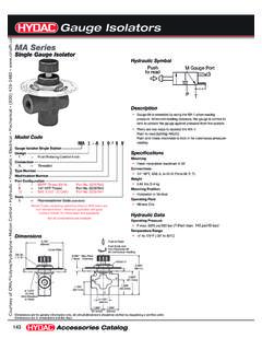
4 R900008158 is included in the scope of ) Not available for type-tested safety valves of sizes 8, 15 and ) Not available for type-tested safety ) For the selection of the Pressure rating, please observe the characteristic curves and notes on page 6!7) For versions G and P , only available as SO292 , see pages 7 and 10! * Further details in clear textPEDNo code = Without type examinationE = Type-tested safety valve in accordance with PED 97/23/ECPipe connectionNo code = Pipe thread to ISO 228/112 = SAE thread Seal materialNo code = NBR sealsV = FKM seals(other seals on request)Attention!Observe compatibility of seals with hydraulic fluid used!Courtesy of CMA/Flodyne/Hydradyne Motion Control Hydraulic Pneumatic Electrical Mechanical (800) 426-5480 Bosch Rexroth AG HydraulicsType DBD RE 25402 relief valves of type DBD are direct operated seat serve to limit a system valves basically consist of sleeve (1), spring (2), pop-pet with damping piston (3) ( Pressure rating 25 to 400 bar) or ball (4) ( Pressure rating 630 bar) and adjustment element (5).
5 The system Pressure setting can be infinitely varied by means of adjustment element (5). Spring (2) presses poppet (3) or ball (4) onto its seat. Channel P is connected to the system. The Pressure prevailing in the system acts on the poppet area (or ball).When the Pressure in channel P rises above the value set on spring (2), poppet (3) or ball (4) opens against spring (2). Hy-draulic fluid can now flow from channel P into channel T. The stroke of poppet (3) is limited by embossment (6).To obtain good Pressure settings over the entire Pressure range, the entire Pressure range was subdivided into 7 pres-sure ratings. A Pressure rating corresponds to a certain spring, which can be used for setting a maximum operating Pressure . Type for Pressure rating 25 to 400 bar (poppet seat valve)SymbolType DBDH 10 K1X/..Version for Pressure rating 630 bar (ball seat valve, NG10 only)Function, section, symbolCourtesy of CMA/Flodyne/Hydradyne Motion Control Hydraulic Pneumatic Electrical Mechanical (800) 426-5480 Bosch Rexroth AGRE 25402 Type DBD5/16 technical data (for applications outside these parameters, please consult us!)
6 HydraulicMaximum operating Pressure Inletbar [psi]400 [5800]630 [9150]400 [5800]315 [4568] Outletbar [psi]315 [4568]315 [4568]315 [4568]315 [4568]Maximum flow (standard valves )See characteristic curves on page 6 Hydraulic fluidMineral oil (HL, HLP) to DIN 51524 1); fast bio-de-gradable hydraulic fluids to VDMA 24568 (see also RE 90221); HETG (rape seed oil) 1); HEPG (polyg-lycols) 2); HEES (synthetic esters) 2); other hydraulic fluids on requestHydraulic fluid temperature range C [ F] 30 to +80 [ 22 to +176] (NBR seals) 15 to +80 [5 to 176] (FKM seals)Viscosity rangemm2/s [SUS]10 to 800 [60 to 3710]Permissible max. degree of contamination of the hydraulic fluid - cleanliness class to ISO 4406 (c)Class 20/18/15 3)1) Suitable for NBR and FKM seals2) Suitable only for FKM seals3) The cleanliness classes specified for components must be adhered to in hydraulic systems.
7 Effective filtration prevents malfunction and, at the same time, prolongs the service life of components. For the selection of filters, see data sheets RE 50070, RE 50076, RE 50081, RE 50086, RE 50087 and RE and 81015 and 2025 and 30 WeightSee pages 7, 9 and 11 Installation positionOptionalAmbient temperature range C [ F] 30 to +80 [ 22 to +176] (NBR seals) 15 to +80 [5 to 176] (FKM seals)Minimum strength of housing materialsHousing materials must be selected so that sufficient safety is provided under all conceivable operating conditions ( with regard to compressive strength, thread stripping strength and tightening torques).For deviating technical data for type-tested safety valves , see page 13. Hydraulic backpressures in port T add 1:1 to the response Pressure of the valve set by means of the adjustment notesExample: Pressure adjustment of the valve by means of spring pre-tensioning (item 2 on page 4) pspring = 200 bar Hydraulic backpressure in port T.
8 Phydraulic = 50 bar response Pressure = pspring + phydraulic = 250 barCourtesy of CMA/Flodyne/Hydradyne Motion Control Hydraulic Pneumatic Electrical Mechanical (800) 426-5480 [2][0][4][6][8][10][ ]0[6526][0][1000][12][2000][3000][4000][ 5000][6000]45040020030010050501001502002 5000[6526][0][1000][2000][3000][4000][50 00][6000][10][0][20] [30][40] [50][66][60]5004003002001005020406080100 1200[4][0][8][12][16][20][ ][24]0[0][1000][2000][3000][4000][5000][ 6000][28]600650[7000][8000][9427]1350300 200501001002003003500[0]0[5076][0][1000] [2000][3000][4000]150250[ ][10] [20] [30] [40] [50] [60] [70] [80]6/16 Bosch Rexroth AG HydraulicsType DBD RE 25402 in l/min [US gpm] Flow in l/min [US gpm] Flow in l/min [US gpm] Flow in l/min [US gpm] Operating Pressure in bar [psi] Operating Pressure in bar [psi] Operating Pressure in bar [psi] Operating Pressure in bar [psi] NG6NG15 and 20 Attention!
9 The characteristic curves are valid for output Pressure = zero over the entire flow range and were measured without housing resistance! The characteristic curves are only valid under the specified ambient and temperature conditions. It must be noted that deviations in the boundary conditions have an influence on the characteristic curve! The characteristic curves refer to the given Pressure ratings ( 200 bar). The greater the difference between the set Pressure value and the nominal Pressure rating ( < 200 bar), the greater is the Pressure increase as the flow and 10NG25 and 30 Characteristic curves (measured with HLP46, oil = 40 C 5 C [104 F 9 F])1 = lowest settable Pressure = Pressure rating 630 bar [9150 psi] (NG10 only)Courtesy of CMA/Flodyne/Hydradyne Motion Control Hydraulic Pneumatic Electrical Mechanical (800) 426-5480 (P)PT(P)PTD1D4; T2L2L1L4L5L3B1B2H2H1D2; T1B1342D31,5[ ]== Bosch Rexroth AGRE 25402 Type DBD7/16 Unit dimensions: Threaded connection (dimensions in mm [inch]) element S (example) Set screw with hexagon and protective cap.
10 Hexagon socket (up to NG20) Hexagon head (NG25 and 30)2 Nameplate34 valve mounting bores4 Additional port (P), optional ( for Pressure mea-surement); not possible for NG10, Pressure rating > 400 bar (= version SO292 ). For dimensions, see D4, for tightening torques, see table belowFor versions and dimensions of the adjustment elements, see pages 8 and 9 Tightening torques MA in Nm [ft-lbs] for screws 1)NGB1B2 D1D2 D3D4 Plug screw (4)Pipe fittings645 [ ]60 [ ]25 [ ]M66,6 [ ]G1/430 [22]60 [44]860 [ ]80 [ ]28 [ ]M89 [ ]G3/840 [29]90 [66]1060 [ ]80 [ ]34 [ ]M89 [ ]G1/260 [44]130 [95]1570 [ ]100 [ ]42 [ ]M89 [ ]G3/480 [59]200 [147]2070 [ ]100 [ ]47 [ ]M89 [ ]G1135 [99]380 [280]25100 [ ]130 [ ]56 [ ]M1011 [ ]G1 1/4480 [354]500 [368]30100 [ ]130 [ ]65 [ ]M1011 [ ]G1 1/2560 [413]600 [442]NGH1H2L1L2L3L4L5L6T1T2 Weight, ca. in kg [lbs]625 [ ]40 [ ]80 [ ]4 [ ]15 [ ]55 [ ]40 [ ]20 [ ]10 [ ]12 [ ] [ ]840 [ ]60 [ ]100 [ ]4 [ ]20 [ ]70 [ ]48 [ ]21 [ ]15 [ ]12 [ ] [ ]1040 [ ]60 [ ]100 [ ]4 [ ]20 [ ]70 [ ]48 [ ]21 [ ]15 [ ]14 [ ] [ ]1550 [ ]70 [ ]135 [ ]4 [ ]20 [ ]100 [ ]65 [ ]34 [ ]18 [ ]16 [ ] [ ]2050 [ ]70 [ ]135 [ ] [ ]20 [ ]100 [ ]65 [ ]34 [ ]18 [ ]18 [ ] [ ]2560 [ ]90 [ ]180 [ ] [ ]25 [ ]130 [ ]85 [ ]35 [ ]20 [ ]20 [ ] [ ]3060 [ ]90 [ ]180 [ ] [ ]25 [ ]130 [ ]85 [ ]35 [ ]20 [ ]22 [ ] [ ]1) The tightening torques are standard values, referred to the maximum operating Pressure and under the assumption that a torque wrench is used (tolerance 10%).