Transcription of FRAMING AND CLOSING IN - Forest Products Laboratory
1 Page Recommended nailing practices .. 38 Exterior wall sheathing.. 65 Floor FRAMING .. 38 Factors in design ( 38 ), Sill plate ( 39 ), Posts and girders ( 39 ), Center beam ( 40 ), Built-up wood beams ( 41 ), Steel I-beams ( 41 ), Beam-joist installation ( 41 ), Floor joists ( 42 ), Header joist ( 45 ), Glued floor design ( 45 ), Bridging ( 47 ), Details at floor openings ( 47 ), Floor FRAMING at projections ( 48 ), FRAMING details for plumbing, heating, and other utilities ( 49 ), Bathtub FRAMING ( 49 ), Cutting floor joists ( 49 ), FRAMING for heating ducts ( 50 ), Wiring ( 50 ). Stairways .. 50 Construction ( 50 ), Stairway design ( 52 ), Landings ( 54 ), FRAMING for stairway opening ( 54 ), Service stairs ( 55 ), Main stairway ( 58 ), Attic folding stairs ( 60 ), Exterior stairs ( 61 ).
2 Floor sheathing .. 61 Plywood ( 61 ), Reconstituted wood panels ( 62 ), Boards ( 62 ). Types of sheathing ( 65 ), Comer bracing ( 71 ), Installation of sheathing ( 71 ), Sheathing paper ( 72 ), Air infiltration barrier materials ( 72 ). Ceiling and roof FRAMING .. 12 Roof designs ( 72 ), Manufactured wood roof trusses ( 73 ), Ceiling joists and rafters ( 78 ). Roof sheathing .. 83 Plywood ( 83 ), Structural flakeboard ( 84 ), Board ( 84 ), Plank roof decking ( 86 ), Fiberboard roof decking ( 86 ), Gable ends ( 87 ), Chimney openings ( 87 ). Roof coverings .. 87 Ice dams ( 88 ), Shingles ( 88 ), Built-up roofs ( 94 ), Other roof coverings ( 94 ), Finish at the ridge and hip ( 94 ). Skylights .. 94 Exterior wall FRAMING .. 62 Requirements ( 62 ), Platform construction ( 62 ), Second-story FRAMING ( 64 ), Window and door FRAMING ( 64 ).
3 37 Chapter 3 FRAMING AND CLOSING IN FRAMING and CLOSING In The sections contained in this chapter address the tasks related to erecting the structural FRAMING for the house and creating an enclosure that provides some degree of protection from the elements. Recommended Nailing Practices Wood members are most commonly joined together with nails, but on occasion metal straps, lag screws, bolts, staples, and adhesive can be used. Proper fastening of frame members and covering materials provides rigid- ity and strength. For example, proper fastening of inter- secting walls usually reduces cracking of plaster at the inside comers. The recommended number and size of nails, shown in the technical note on nailing schedule, is based on good nailing practices for the FRAMING and sheathing of a well- constructed wood-frame house.
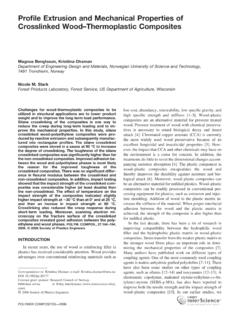
4 Sizes of common wire nails are shown in figure 26. Houses that are located in hurricane areas should be provided with supplemental fasteners called hurricane straps or tiedowns to anchor the floor, walls, and roof to the foundation. Wind, snow, and seismic loads are one of the special topics discussed in chapter 8. Floor FRAMING Floor FRAMING consists of columns or posts, beams, sill plates, joists, and subfloor. Assembled on a foundation, they form a level anchored platform for the rest of the house and a strong diaphragm to keep the lateral earth pressure from pushing in the top of the foundation wall. The columns or posts and beams of wood or steel that support the joists over a basement are sometimes replaced by frame or masonry walls when the basement area is divided into rooms.
5 Floors of the second story are gener- ally supported on load-bearing walls in the first story. Wood-frame houses may also be constructed over a crawl space with floor FRAMING similar to that used over a base- ment or on a concrete slab as shown in the section on foundations. Factors in design An important consideration in the design of a wood floor system is wood shrinkage. When wood with a high moisture content is used, subsequent shrinkage can result in cracks, doors that stick, and other problems. This is particularly important where wood beams are used, Figure 26 Common nails. because wood beams may shrink and foundation walls will not. In beams and joists used in floor FRAMING , mois- ture content should not exceed 19 percent; about 15 per- cent is a much more desirable maximum.
6 Dimension material can be obtained at either of these moisture con- tents, when specified. Grades of dimension lumber vary considerably with wood species. For the specific uses described in this pub- lication, material is divided into five categories. The first category is the highest quality, the second is better than average, the third average, and the fourth and fifth for more economical construction. Joists and beams are usually of a species of second category material, while sills and posts are usually of third or fourth category. (See technical note on lumber grades.) Stairways and other openings that penetrate the floor structure should be located so as to interrupt as few mem- bers as possible.
7 Stairways should be oriented parallel to floor joists so that only one joist need be interrupted with 24-inch on-center joist spacing. Wherever possible, the stair opening should be coordinated with a normal joist location on at least one side. Stairways should never interrupt a structural beam or bearing wall when it can be avoided. The stairway design should be completed before floor FRAMING begins, because the stairwell opening must be 38 framed at the time the floor is constructed. The rough- framed opening for a stairwell should be 1 inch wider than the desired finished stairway width. The length of the opening must be accommodated to tread run and stair rise, which in turn are governed by total rise.
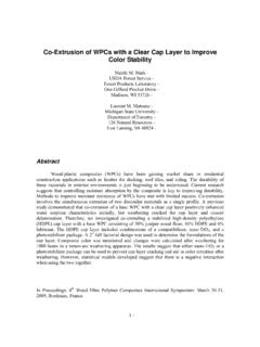
8 Other openings such as those for clothes chutes and flue hole should also be located to avoid interrupting FRAMING members. Two-foot on-center spacing of joists generally provides ample clearance for such openings. Sill plate A wood-frame floor system should be anchored to the foundation to resist wind forces acting on the structure. This is usually done with a 2- by 6-inch sill plate attached to the foundation by -inch anchor bolts at 8-foot inter- vals. Floor joists are toenailed to the sill plate (fig. 27A). The sill plate may also be attached with anchor straps that are embedded in the foundation in the same manner and at the same spacing as anchor bolts. These devices do not require holes in the sill plate; metal straps are simply bent up around the plate and nailed.
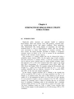
9 anchor straps are less exacting and do not interfere with other FRAMING as con- ventional bolts often do. Figure 27 Anchoring floor system to poured concrete foundation wall: Sill plates may be entirely eliminated where the top of a foundation of poured concrete (fig. 27B) or concrete block (fig. 28B) is sufficiently level and accurate. Joists may bear directly on a solid concrete wall or on a top course of solid concrete block. They may also bear directly on cross webs of hollow core block or on cores that have been filled with mortar. Where the sill plate is omitted, anchorage of the floor system may be provided by anchor strap devices, as described above. The straps should be spaced to coincide with joist locations so that each may be nailed directly to the side of a joist (fig.)
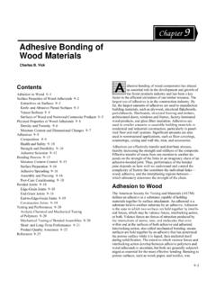
10 28). As noted previously, a foundation of pressure-treated wood does not require a sill plate or special anchor devices. Floor joists bear directly on the top foundation wall plate and are toenailed to provide anchorage. Posts and girders Wood posts or steel columns are generally used in the basement to support wood or steel beams. Masonry piers or wood posts are commonly employed in crawl-space houses. Steel pipe columns can be used to support either wood or steel beams. They are normally supplied with a steel 39 Figure 28 Anchoring floor system to concrete block foundation wall: bearing plate at each end. Secure anchoring to the beam is important (fig. 29). Wood posts should be solid, pressure-treated, and not less than 6 by 6 inches in size for freestanding use in a basement.