Transcription of Frequency counter / Digital Dial - QRP Kits - Pacific Antenna
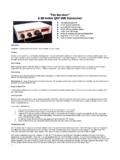
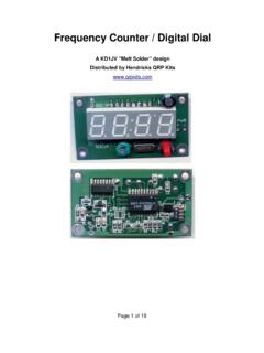
1 Frequency counter / Digital Dial The Digital Dial is primarily intended to be used as a simple means of adding a Digital Frequency read out to single band QRP radios. A programmable IF offset feature allows the counter to measure the VFO Frequency but display the actual operating Frequency . The Digital dial can also be used as a general purpose Frequency counter . It also includes a special crystal matching mode, which allows the matching of crystals used in IF filters to with in 10 Hz of each other. Specifications: Frequency range: 100 kHz to 45 MHzResolution: 100 Hz displayed, 50 Hz internal Update rate: 200 msInput level: 50 mv to 100 mv p-p min, 2 V p-p max. (sensitivity varies with freq)Input impedance: 1 Meg , four digit LED Supply voltage: 8 V min, 14 V maxSupply current: 37 ma, typicalSize: wide, high, deepTable of ContentsSpecifications.
2 1 Assembly:..2 Test and calibration:..5 Trouble shooting:..5 Calibration:..5 Operation:..5As a Frequency counter :..5 Sleep Mode:..6 Activating Sleep Mode: ..6 Waking up the display:..6 Using as a Digital Dial:..6 Programming the IF offset:..6 Entering the IF offset program mode:.7 Connecting the counter to the VFO:..7 Display multiplexing noise on supply Matching mode:..7 Entering Matching Mode:..8 Crystal matching:..8 Mounting the counter it works:.. with SMT parts:..12 Tools:..12 Removing the parts from the :..12 Manual updated 6/8/111 Assembly:Empty the contents of the static bag into a soup or cereal bowel. This will help keep you from losing any of the small parts. In order to make identifying the SMT parts easier, some of the parts have been color coded. The colors indicated on the layout diagram corresponds to the color marked on the SMT carrier that you do not mix up the parts, work with only one type of parts at a time.
3 If there is more than one value used, place all of them before moving onto another. Surface mounted parts are installed first. All of these go on the back side of the board. If this is the first time you've assembled anything using SMT parts, please refer to the Building with SMT parts appendix at the end of the : Do not use your usual solder, which is often in diameter. Get some solder, silver bearing is best. Radio Shack sell small rolls of this kind of solder. Use these pictures to help locate and identify parts. Zoom in with the magnifier in the pdf viewer for a closer look. 2 Assembly: Back sideRecommended parts placement order shown in table:Note: Avoid pushing leads on Q1 and Q2 sideways when soldering, or it can damage the internal connections. Note beveled edge on U1 for proper orientation . Part number will also be in same orientation as shown in diagram.
4 Note white line on D1 package, which will face towards the line above the D1 outline in diagram above. 3 colorlocationmarkingstypequantityORANGEQ 16T fNPN1 BLUEC1 to 6 None, uFd cap6 ORANGEC7 None, tan22 pFd cap1R2 - R5 to 9R11051 Meg1R3104100K 1R41021K1L1 None, uHy1----------D1S2 49 Diode1----------U174HC4017counter1------ -----U2 Tiny2313 MPU1-----------U38C3M5V reg1 Front side parts: Display:The display is soldered into place first. This requires a little rework before it can be done. All but the two left most pins need to be bent out at a 90 angle to the body as can be seen in the photo to the left. The part numbering on the side of the display indicates the bottom side, the side which will mount towards S1, X1 and C9. Simply fold the leads over with your thumb or needle noise pliers.
5 Once the leads are bent over, clip them back about half their length, so that the pins do not go beyond the edge of the pads on the board. Now the display can be soldered to the pads on the board. The two display leads which have not been bent to a right angle go into the two holes in the board as shown in the placement diagram above. This helps to ensures the display will be not end up crooked on the board. However, before soldering the pins in place, make sure it is parallel to the board and the corners of the display are flat to the board. Once the display is soldered into place, proceed with the four remaining through hole parts. Note: the flat side of C9 mounts towards the line in the outline on the board. Assembly of the counter is now complete. Now is a good time to inspect your workmanship and look for any solder connections you might have missed making.
6 Look closely at both ends of the chip resistors and capacitors. 4C9 Green trimmer C847 uF/ 16 VLong lead + MHz crystalS1 TACT switchTest and calibration:Connect up a power supply, a 9 V battery will do for now. When power is applied, the display should light up with four eights and four decimal points for a couple of seconds. [ ] This is the display test. Once the display test is over, the counter will be in the kHz Frequency counter mode. Due to stray pick up by the high impedance input, you will see random numbers flickering on the display. Short the [SIG IN] terminals and the display should now read all zeros. [ ] Confirm Mode switch operation by clicking and verify display changes to MHz range [ ] Clicking and holding close the Mode switch for one second should turn off the display. Clicking again turns the display back on.
7 Trouble shooting:There isn't a whole lot which can go wrong with this board. If it does not work first time, there is a chance the problem is with the soldering of parts. Therefore, this is what you need to look for first. The other .001% is a misplaced part. Calibration:The counter needs to be calibrated before it will measure accurately. This is done by adjusting the green trimmer on the front of the board. The trimmer has a range of about +/- 700 Hz at 10 MHz. The exact range is dependent on the Frequency inputed to the counter . Higher frequencies will have a larger apparent range than lower ones. If no accurate Frequency source is available for calibration, centering the trimmer cap in its adjustment range (45 degree turn from factory setting) will put it reasonably close. An accurate signal source is required and should be done at the highest Frequency available, which is in the range of the counter (45 MHz).
8 For most of you, the most accurate signal source you may have available is your commercial Big Rig , and the highest Frequency available will be in the 10 M band. In CW mode, most rigs transmit on the Frequency indicated by the dial. You should of course, transmit into a dummy load. If the dummy load is well shielded, you might have to put a coax T connector in series with the cable going to the dummy load and add a short Antenna wire to the tap. With a similar short Antenna on the counter input, you will likely get enough signal to get a stable display on the counter . A more reliable method might be to use a resistor divider across the dummy load, say a 100 K in series with a 1 K resistor. The counter input would be connected across the 1 K resistor and the 100 K to the top of the dummy load. Start with as little power output from the rig as possible, then if needed, increase to get a stable reading on the counter .
9 Operation:The Digital dial is controlled by a single switch, which we will call the Mode switch. This switch may have more than one function, depending on the mode in which the Digital dial is being used. As a Frequency counter :The first time power is applied to the Digital dial, it will power up in the Frequency counter mode. Since the counter can count up to 45 MHz and there are only four digits of display, there is a display shift function. On power up, the kHz and 100 Hz digits are displayed. This is indicated by the decimal point being to the right of the third digit. The most significant digit is indicating 100 kHz and the least significant digit is indicating 100 Hz, or .1 kHz. To display the MHz digits, click the Mode switch. The decimal point will now shit the the left one digit, so that it is to the right of the second digit.
10 The display is now indicating 10's of MHz in the most significant digit and 10 kHz in the least significant digit. 5 Sleep Mode:In order to reduce current consumption when the counter isn't being used, there is a Sleep Mode function. This turns off the display and powers down the MPU. The input circuits and counter are still under power, so current is reduced to only about 15 ma. Activating Sleep Mode: Click and hold the Mode switch for about one (1) second, until the display goes blank. Waking up the display:Click the Mode switch again to wake up the MPU and turn the display back as a Digital Dial:In most radios, an IF offset will need to be programmed into the counter in order to indicate the operating Frequency of the rig. This is because the IF Frequency is often a fractional MHz Frequency , such as MHz. If the IF Frequency has no fractional component, such as MHz, there is no real need to program an offset, provided one is only interested in reading the kHz part of the operating Frequency .