Transcription of Friction Losses between Piston Ring-Liner …
1 International Journal of Scientific and Research Publications, Volume 3, Issue 6, June 2013 1 ISSN 2250-3153 Friction Losses between Piston Ring-Liner assembly of Internal Combustion Engine: A Review Bedajangam S. , N. P. Jadhavb a Mechanical Department, SAOE, Kondhwa, India b Mechanical Department, SAOE, Kondhwa, India Abstract- In IC engine Piston ring Friction Losses account for approximately 20% of total mechanical Losses as reported in the literature. A reduction in Piston ring Friction would therefore result in higher efficiency, lower fuel consumption and reduced emissions. To reduce these Losses , various parametric approaches are made particularly at design stage and experimental level. The goal of this study was develop Piston ring designs to improve engine efficiency, without adversely affecting oil consumption, blow by, wear and cost.
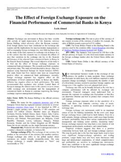
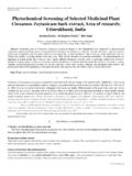
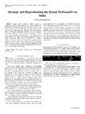
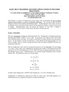
2 Thus it provides characterization of a pressure balance in terms of effective area and distortion coefficient of the Piston and cylinder. The models are for specific Piston Ring-Liner system with different capacity. The variable parameters are Piston velocity, engine speed, oil viscosity, gas pressure, crank angle film thickness and coefficient of Friction . Non variable parameter are system constant, bore diameter, ring tension, ring width, compression ratio, reciprocating mass, Piston ring area and Piston ring profile. The major assumptions for developing models are either hydrodynamic lubrication theory or mixed lubrication theory of Reynolds equation. Index Terms- Piston Velocity, Engine Speed, Oil viscosity, Oil film Thickness etc. I. INTRODUCTION significant share of the total power loss in modern internal combustion engine is due to the Friction interaction between the upper compression ring and cylinder wall as shown in (Figure 1).
3 Figure 1: assembly of lubricating pair Piston ring and Cylinder Wall Main part of the study on the basis, the lubrication of the Piston ring has been an important research matter for many years because it is extensively accepted. The Piston ring pack in an internal combustion engine typically consists of three circular rings located in grooves in the Piston . The rings move with the Piston along the cylinder liner during engine operation. The primary function of Piston is to maintain an effective gas seal between the combustion chamber and crankcase. The reciprocating motion of Piston ring in cylinder creates drastic change in the pressure, the combustion event generates large amount of heat. The second function of Piston Ring-Liner assembly is to transfer this heat from the Piston in to the cylinder wall.
4 These can be effective by considering alloy materials which may lead to prolong life of the cylinder liner and Piston . The third function of Piston ring assembly is to limit the amount of oil that transported from the crankcase to the combustion chamber by oil control ring . The Piston ring & cylinder wall interface is particularly interesting as it has been estimated to account for 18-20% of the total engine mechanical Friction [5] due to the most severe environment in terms of temperature and load; so much effort has been directed to this particular ring . Because of the Piston always in an unsteady state, the frictional behavior of this Piston ring is very complex. Due to the variation in oil supply to the different Piston rings throughout the engine cycle, each ring encounters different modes of lubrication while traveling along the liners.
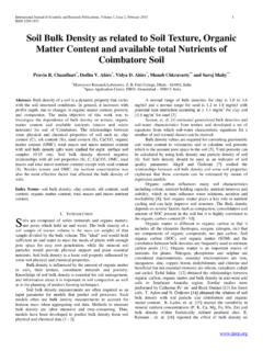
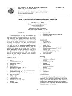
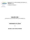
5 If a sufficient amount of oil exists on the liner to support a load, hydrodynamic lubrication conditions are present. Otherwise the load from the ring on the liner is supported by contact between the asperities on the two surfaces and boundary lubrication condition are said to be present. These modes of lubrication have a profound effect on the magnitude of the Friction force generated by the motion of the rings along the liner . A schematic of a typical lubrication condition between the ring and the liner is shown Figure 2. A International Journal of Scientific and Research Publications, Volume 3, Issue 6, June 2013 2 ISSN 2250-3153 Figure 2 Lubrication Conditions Encountered by Piston rings. As shown in figure, due to the roughness of the surfaces in contact, it is possible for certain portions of the two surfaces to have asperity contact and for other parts to be sufficiently lubricated such that the ring is supported by load from the oil film.
6 To simplify this situation, the modes of lubrication are typically characterized by the spacing between nominal lines that define smooth surfaces representing the average of the asperities. Depending on the distance between the nominal lines, h(x), three different modes of lubrication are possible; a) Pure Hydrodynamic Lubrication b) Mixed Lubrication c) Pure Boundary Lubrication In pure hydrodynamic lubrication, a sufficient amount of oil separates the two surfaces such that there is no asperity contact between them. The transition from pure hydrodynamic lubrication to mixed lubrication occurs when the following criteria is met; Where, is the combined roughness between the ring surface and the liner [10]. In mixed lubrication, there is oil between the two surfaces in contact, but there is also portion of the ring and liner surfaces between which the spacing is sufficiently small that satisfy by equation , and therefore these parts of the surfaces are also considered to be in boundary contact.
7 The transition between mixed lubrication and pure boundary lubrication occurs when the wetting between the ring and the liner completely disappears, and there is therefore no more oil between the ring & the liner . The Friction force between the ring and the liner is determined as follows; The shear stress, , appearing in the above equation is defined by applying conservation of mass and momentum to a fluid element under the ring surface. The Friction force can be expressed as a function of the oil film height and width; Therefore, once the oil film height and width are determined from the solution of the governing equation, the Friction force from hydrodynamic lubrication can be determined. Pure boundary Friction occurs when no oil exists between the ring and the liner , and therefore the load from the ring on the liner is completely supported by asperity contact.
8 In this case, the Friction force is given by the following expression; Where is the Friction coefficient governed by the surface properties, x1 and x2 define the boundaries of the portion of the ring liner surfaces that are in asperity contact according to equation 1, and is the contact pressure between the two surfaces. The contact pressure is given by the following empirical fit used by Hu based on Greenwood-Tripp s theory[11]; Where depends on asperity and material properties and z is a correlation constant described in [8]. Mixed Friction , as would be expected, the Friction between the ring and the liner in mixed lubrication is the sum of the contributions from pure hydrodynamic and pure boundary Friction .
9 Mixed Friction is the calculation as follows; The governing equation describing Piston ring Friction and lubrication that were introduced briefly, The Reynolds equation relates the height, width and shape of the oil film between the ring and the liner with the pressure gradient that is generated. ( ) For the unsteady term in the Reynolds equation can be neglected everywhere in the cycle expect near dead centers where the Piston velocity U becomes very small. With this simplification, valid in all parts of the cycle other than at end strokes equation reduce to; ( ) II. EFFECT OF ENGINE OPERATING CONDITIONS ON SOURCES OF Friction Modern internal combustion engines operate in a variety of speed and load conditions depending on their application.
10 In passenger cars and transport trucks, loads and speeds vary considerably due to the variety of driving condition encountered. Racing engines typically operate at high speed and high loads. Stationary power generation engines operate in high load, low speed conditions because the high load generates more power and the low speed is needed to interface with the electric generator and the power gird. Both engine speed and load affect the Friction generated between the Piston rings and the liner . International Journal of Scientific and Research Publications, Volume 3, Issue 6, June 2013 3 ISSN 2250-3153 A. Effect of engine speed The effect of engine speed on the Friction generated between the Piston rings and the liner as define equation. The pressure gradient integrated over the wetted width typically ends up resulting in a much smaller contribution.