Transcription of Friction Stir Welding of Ferrous and Nickel Alloys
1 CHAPTER 6 Friction stir Welding of Ferrous and Nickel AlloysCarl D. Sorensen and Tracy W. NelsonDepartment of Mechanical Engineering, Brigham Young UniversityFRICTION stir Welding (FSW) is asolid-state joining process invented by TheWelding Institute of Cambridge, England (Ref1). In the FSW process, a rotating tool contain-ing a pin and a shoulder is plunged into the jointbetween two workpieces, generating heat byfriction. Once the heat has built up to the desiredlevel, the tool is translated along the joint. Plas-ticized base material passes around the tool ,where it is consolidated due to force applied bythe shoulder of the stir Welding has been applied to met-als with moderate melting points. Initially, FSWwas applied primarily to aluminum Alloys ,which could be easily welded due to the rela-tively low softening temperatures of thesealloys.
2 Other relatively soft metals, such as cop-per, lead, zinc, and magnesium, have also beenwelded. In contrast, for a number of years it wasdifficult to weld Ferrous Alloys and other high-softening-temperature metals due to the lack ofsuitable tool recently, there were no tool materialsthat would stand up to the high stresses and tem-peratures necessary for FSW of materials withhigher melting points, such as steels, stainlesssteels, and Nickel -base Alloys . In 1998, tungstenalloys and polycrystalline cubic boron nitride(PCBN) were developed to create FSW tools foruse in steel , stainless steel , titanium Alloys , andnickel-base Alloys . Properties of the resultantwelds have been shown to be some issues remain (primarily limitedtool life with tungsten-base tools), FSW hasbeen demonstrated as a technically and eco-nomically feasible process in high-temperaturematerials.
3 This chapter summarizes researchwork performed at a number of different labora-tories to make FSW of high-temperature mate-rials a reality. It covers the development of suit-able tools, Welding equipment, and weldingprocedures, describes the characteristics of theresulting weldments, and describes the varietyof materials that have been tested with the tool MaterialsThe requirements for an FSW tool in high-temperature materials (HTM) are , the tool must maintain sufficientstrength to constrain the weld material at soft-ening temperatures in excess of 1000 C (1830 F). Perhaps less apparent, the tool mustalso be resistant to fatigue, fracture, mechanicalwear, and chemical reactions with both theatmosphere and the weld material. To date, twoclasses of materials have been found that meetthese requirements: refractory metal tools andsuperabrasive Metal first class oftool materials to be used for FSW of HTM wererefractory metal tools.
4 Initially, the tool materi-als were considered proprietary. Eventually,however, the composition of the tools was used as a tool material in manyof the early welds performed (Ref 2). Tungstenappeared to have sufficient hot strength to serve 2007 ASM International. All rights stir Welding and Processing (05112G) / Friction stir Welding and Processingas an FSW tool but suffered problems on theplunge due to its high ductile-to-brittle transitiontemperature. This necessitated preheating of thetool to temperatures above 300 C (570 F) andthe drilling of a pilot hole for the tool (Ref 3).Later tool materials included additions of upto 25% Re to tungsten, which lowered the tran-sition temperature to below room tools show increased frac-ture resistance and improved wear resistancecompared to pure tungsten and appear to havebecome the most widely used refractory of production processes continuesto improve the tool life of tungsten-rheniumtools.
5 Molybdenum has been used on at leastone occasion as a tool material for FSW of steel (Ref 4).Early tungsten and tungsten-rhenium toolsshowed a tendency to wear rapidly in the weld,leading to macroscopic inclusions of tool mate-rial in the weld zone. Later tools were muchmore resistant to this problem, but the toolmaterial often continues to dissolve in the weld,leaving a tungsten-enriched stir zone. Further-more, some researchers report that microstruc-tural changes in the tool indicate ongoing defor-mation during metal tools have been used toweld low-carbon steels, carbon-manganesesteels, austenitic stainless steels, and ferriticstainless tools show good fracturetoughness and can be used for relatively thickwelds (up to 13 mm in a single pass).
6 Reportedtool life ranges from a quarter meter (tens ofinches) up to approximately 4 m (over 10 ft).Superabrasive second class oftool materials used for FSW of HTM is su-perabrasives. Superabrasives are materials thatare formed in presses under extreme tempera-ture and pressure. The two superabrasives thathave been used in FSW are polycrystalline dia-mond (PCD) and PCBN. Both materials consistof small crystals of ultrahard material (diamondor CBN) bonded together in a skeletal matrixwith a second-phase material that serves as acatalyst for the formation of the matrix. Refer-ence 5 gives a summary of the characteristics ofsuperabrasive diamond has been used foraluminum-matrix composites reinforced withparticulate silicon carbide, boron carbide, oralumina.
7 It also shows promise as a tool mate-rial for Welding titanium, although this work isonly in a preliminary cubic boron nitride has beenused to weld carbon steels, carbon-manganesesteels, high-strength, low-alloy (HSLA) steels,high-strength pipeline steels, austenitic stainlesssteels, duplex stainless steels, dual-phase steels, Nickel -base Alloys , and other exotic Alloys . Ithas been tested in titanium Alloys , with incon-sistent results. At times, it performs well; at oth-ers, chemical reactions with the workpiececause rapid materials can be made only inrelatively small pieces, due to the high pressurerequired for manufacturing. Furthermore, thesematerials are very difficult or impossible tobraze. Therefore, superabrasives are used in acomposite tool design, as described by Ref trials of PCBN tools in 316L stainlesssteel showed tool life of 1 to 4 m (3 to 13 ft),with life limited by fracture.
8 Continued effortsat improving the design of the composite tools,together with improvements in the grade of thePCBN, have greatly reduced the tendency of thetool to fracture and have increased its life sig-nificantly (Ref 6). The most recent tool life teston PCBN tools showed a tool life of 80 m (260ft) in 1018 cubic boron nitride tools pro-duce an exceptionally smooth surface on theweld. This is thought to be due to the low coef-ficient of Friction between PCBN and the major limitation in PCBN tools is themaximum depth of the weld. Although a pin 13 mm ( in.) in length has been tested, forpractical purposes, the maximum depth of weld-ing at the present time is 10 mm ( in.). Ongo-ing efforts in the design of PCBN tools shouldlead to increases in pin length. MegaStir Tech-nologies, the provider of PCBN tools, has plansto achieve a 13 mm weld depth within a the past several years, significantefforts were expended on developing tougher,more wear-resistant grades of PCBN (Ref 6).
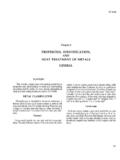
9 Efforts to understand the effects of differentbinder phases, ratio of CBN to binder phase, andgrain size distributions of CBN on performancewere investigated. Performance was evaluatedvia a turning test on 304L stainless steel . Thosegrades exhibiting greater wear resistance in theturning tests were subsequently evaluated viaFSW in 304L to compare wear results and eval-uate PCBN grade-development program wasquite successful in that tougher, more wear-resistant grades of PCBN were developed. Inaddition to improved wear resistance, theimproved toughness of the new grades has 2007 ASM International. All rights stir Welding and Processing (05112G) 6: Friction stir Welding of Ferrous and Nickel Alloys / 113 Fig. features produced on polycrystalline cubic boron nitride Friction stir processing tools, including (a) flats, (b) helicalthreads, and (c) a combination of convex scrolled shoulder and helical threaded pinenabled both deeper weld penetration (up to 12 mm, or in.)
10 And threaded-type featuresto be incorporated into the tool design. Thesefeatures are illustrated in Fig. FSW EquipmentThe FSW equipment for high-temperaturematerials requires improved cooling, higher-precision spindles, and increased machine stiff-ness compared to that required for Welding zone tempera-tures frequently reach 900 to 1200 C (1650 to2190 F). Further, the materials used for the tool (either tungsten Alloys or tungsten carbideshanks) have high thermal conductivity relativeto the tool steel commonly used for prevent damage to the spindle bearings and toestablish a consistent thermal environment forthe tool , cooling of the tool shank is different methods for cooling the toolhave been used. In the first, a hollow drawbar isused to conduct coolant directly onto the backend of the tool shank.