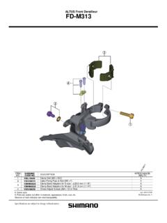
Transcription of Front derailleur - Shimano
1 (English) DM-RAFD001-02. Dealer's Manual ROAD MTB Trekking City Touring/. URBAN SPORT E-BIKE. Comfort Bike Front derailleur DURA-ACE. FD-R9100. ULTEGRA. FD-R8000. 105. FD-5801. Procedures for cable tension adjustment and top adjustment differ from those of previous models. Be sure to read this dealer's manual thoroughly before use, and follow it for correct use. CONTENTS. IMPORTANT 3. TO ENSURE 4. LIST OF TOOLS TO BE 7. 9. Brazed-on Band Installation of the Front derailleur using a band adapter (SM-AD91)..13. 15. Connection and securing of inner Adjustment of cable Top Low Routing and cutting excess Troubleshooting 24. Replacing the skid 2. IMPORTANT NOTICE. IMPORTANT NOTICE. This dealer's manual is intended primarily for use by professional bicycle mechanics.
2 Users who are not professionally trained for bicycle assembly should not attempt to install the components themselves using the dealer's manuals. If any part of the information on the manual is unclear to you, do not proceed with the installation. Instead, contact your place of purchase or a local bicycle dealer for their assistance. Make sure to read all instruction manuals included with the product. Do not disassemble or modify the product other than as stated in the information contained in this dealer's manual. All dealer's manuals and instruction manuals can be viewed on-line on our website ( ). Please observe the appropriate rules and regulations of the country, state or region in which you conduct your business as a dealer.
3 For safety, be sure to read this dealer's manual thoroughly before use, and follow it for correct use. The following instructions must be observed at all times in order to prevent personal injury and physical damage to equipment and surroundings. The instructions are classified according to the degree of danger or damage which may occur if the product is used incorrectly. DANGER. Failure to follow the instructions will result in death or serious injury. WARNING. Failure to follow the instructions could result in death or serious injury. CAUTION. Failure to follow the instructions could cause personal injury or physical damage to equipment and surroundings. 3. TO ENSURE SAFETY TO ENSURE SAFETY. WARNING. Be sure to follow the instructions provided in the manuals when installing the product.
4 It is recommended to use genuine Shimano parts only. If parts such as bolts and nuts become loose or damaged, the bicycle may suddenly fall over, which may cause serious injury. In addition, if adjustments are not carried out correctly, problems may occur, and the bicycle may suddenly fall over, which may cause serious injury. Be sure to wear safety glasses or goggles to protect your eyes while performing maintenance tasks such as replacing parts. After reading the dealer's manual thoroughly, keep it in a safe place for later reference. Be sure to also inform users of the following: Be careful not to let the hemming of your clothes get caught in the chain while riding. Otherwise you may fall off the bicycle. NOTE. Be sure to also inform users of the following: If gear shifting operations cannot be carried out smoothly, clean the derailleur and lubricate all moving parts.
5 When the chain is in any of the positions shown in the illustration, the chain may come into contact the Front chainring or Front derailleur and generate noise. If the noise is a problem, shift the chain to the second largest rear sprocket. Double Front chainring Rear sprocket Products are not guaranteed against natural wear and deterioration from normal use and aging. For maximum performance we highly recommend Shimano lubricants and maintenance products. 4. TO ENSURE SAFETY For Installation to the Bicycle, and Maintenance: Use an OT-SP sealed outer casing and cable guide for smooth operation. Grease the inner cable and the inside of the outer casing before use to ensure that they slide properly. Do not let dust adhere to the inner cable.
6 If the grease on the inner cable is wiped off, the application of SIS SP41 grease (Y04180000) is recommended. derailleur side If using a full outer casing, connect the end with the outer cap (resin type) to the derailleur . If using the bicycle in a cold region, use sealed outer cap (resin type) to protect against freezing. Outer cap (resin type) Cap with long tongue If looseness in the links is so great that gear shifting adjustments cannot be made, replace the derailleur . The actual product may differ from the illustration because this manual is intended mainly to explain the procedures for using the product. 5. LIST OF TOOLS TO BE USED. LIST OF TOOLS TO BE USED. LIST OF TOOLS TO BE USED. The following tools are needed for installation, adjustment, and maintenance purposes.
7 Tool Tool 2mm hexagon wrench 5mm hexagon wrench 4mm hexagon wrench 7. INSTALLATION. INSTALLATION. Brazed-on type INSTALLATION. NOTE. With a carbon frame, even the recommended tightening torque may be too tight and cause damage to the frame, or too loose and not sufficiently attached to the frame. For the appropriate torque value, consult with the manufacturer of the completed bicycle or the manufacturer of the frame. Brazed-on type If installing the Front derailleur to a brazed-on type frame, a backup plate must be attached to the seat tube. Always be sure to install the backup plate in order to prevent damage to the frame from the pressure applied by the support bolt of the Front derailleur . Installation of the backup plate There is a backup plate with a curved adhesion surface [1] and one with a flat adhesion surface [2], (A) Tape as shown in the illustrations.
8 Use whichever type matches the shape of the frame. [1] [2]. (A) (A). Check the position where the support (A) Tape bolt directly touches the frame when the (B) Backup plate support bolt of the Front derailleur is being adjusted, and attach the backup (C) Support bolt plate in that position. In addition, avoid positioning the tape that attaches the backup plate to the seat tube in the location where the support bolt directly touches the frame. (B). (A). (B). (C). 9. INSTALLATION. Brazed-on type Installation of the Front derailleur Adjust so that there is a clearance of 1 (A) Chain guide 3mm between the chain guide outer (B) Largest chainring (A) plate and the largest chainring. 1 (z). After this, tentatively tighten the clamp bolt.
9 (B). (z) 1 3mm Adjust the low adjustment bolt and align (A) Front end of chain guide outer the Front end of the chain guide outer plate plate parallel to the surface of the (B) Low adjustment bolt largest chainring. (C) Largest chainring (B) At this point, adjust the chain guide so (D) Rear end of chain guide that its rear end is inside. (z) 1mm (A). 2. (C). (D). (z). To be continued on next page 10. INSTALLATION. Brazed-on type When the adjustment is complete, (A) Clamp bolt tighten the clamp bolt. (A) Tightening torque 5 - 7 N m 3. (A) Adjust the support bolt so that the flat (A) Support bolt portion of the outer plate of the chain guide is parallel to the surface of the largest chainring. NOTE. At that time, make sure that the support bolt is in contact with the backup plate.
10 Adjustment is complete 4. TECH TIPS. Check by holding a hexagon wrench against the flat surface of the largest chainring. 11. INSTALLATION. Band type Band type Adjust so that there is a clearance of 1 (A) Chain guide 3mm between the chain guide outer (B) Largest chainring (A) plate and the largest chainring. 1 (z). After this, tentatively tighten the clamp bolt. (B). (z) 1 3mm Adjust the low adjustment bolt and align the flat portion of the chain guide outer plate (A) Largest chainring parallel to the surface of the largest chainring. (B) Chain guide (C) Low adjustment bolt NOTE. (C). (A). 2 (A). (B) TECH TIPS. Check by holding a hexagon wrench against the flat surface of the largest chainring as shown in the illustration. To be continued on next page 12.