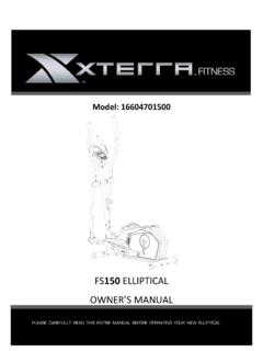
Transcription of FS3.5 ELLIPTICAL - XTERRA Fitness
1 ELLIPTICAL owner S MANUALPLEASE CAREFULLY READ THIS ENTIRE manual BEFORE OPERATING YOUR NEW ELLIPTICAL Table Of Contents12591217 ATTENTION THIS ELLIPTICAL IS INTENDED FOR RESIDENTIAL USE ONLY AND IS WARRANTED FOR THE APPLICATION. ANY OTHER APPLICATION VOIDS THIS WARRANTY IN ITS RegistrationImportant Safety Assembly InstructionsOperation of Your ConsoleProgram OperationManufacturer s Limited WarrantyThank you for your purchase of this quality ELLIPTICAL from XTERRA Fitness . Your new ELLIPTICAL has been manufactured by one of the leading Fitness manufacturers in the world. XTERRA Fitness will do all we can to make your ownership experience as pleasant as possible for many years to come. If you have questions, or if parts are missing or damaged, or you require customer service, call (870) 336-4286. Please have your model number and serial number handy when you take a moment to record where you purchased your machine, as well as the date of purchase for future reference.
2 We appreciate your confidence in XTERRA Fitness and we will always remember that you are the reason that we are in business. Please complete and mail your registration card today and enjoy your new in Health, XTERRA FitnessCongratulations On Your New ELLIPTICAL and Welcome to the XTERRA Fitness Family! Elliptical1 Record Your Serial NumberPlease record the Serial Number of this Fitness product in the space provided NumberRegister Your PurchaseThe self-addressed product registration card must be completed in full and returned to XTERRA Fitness . You can also go to to register RegistrationThis product uses an external power supply. The power supply must be plugged into the power jack, located on the front of the unit near the stabilizer tube. Next, plug the power supply into the appropriate wall outlet. When not in use, it is rec-ommended to unplug the power supply from the wall : If the product has been exposed to cold temperatures, allow the product sit in room temperature to warm up before plugging in the power supply.
3 Failure to do so may result in damage to the display or electronic : Do not operate the product if the power supply, its plug, or its cord has been LocationPurchase ELLIPTICAL To disconnect, turn all controls to the off position, then remove the plug from the outlet. Do not operate equipment on deeply padded, plush or shag carpet. Damage to both carpet and equipment may result. Before beginning this or any exercise program, consult a physician. This is especially important for persons over the age of 35 or persons with pre-existing health conditions. Keep hands away from all moving parts. The pulse sensors are not medical devices. Various factors, including the user s movement, may affect the accuracy of heart rate readings. The pulse sensors are intended only as exercise aids in determining heart rate trends in general. Do not attempt to use your equipment for any purpose other than for the purpose it is intended.
4 Wear proper shoes. High heels, dress shoes, sandals or bare feet are not suitable for use on your equipment. Quality athletic shoes are recommended to avoid leg fatigue. Important Safety InstructionsWhen using an electrical appliance, basic precautions should always be followed, including the following:Read all instructions before using this - To reduce the risk of electric shock:1. Always unplug this appliance from the electrical outlet immediately after using and before - To reduce the risk of burns, fire electric shock, or injury to persons: 1. An appliance should never be left unattended when plugged in. Unplug from outlet when not in use, and before putting on or taking off parts. 2. Do not operate under blanket or pillow. Excessive heating can occur and cause fire, electric shock, or injury to Close supervision is necessary when this appliance is used by, on, or near children, invalids, or disabled Use this appliance only for its intended use as described in this manual .
5 Do not use attachments not recommended by the Never operate this appliance if it has a damaged cord or plug, if it is not working properly, if it has been dropped or damaged, or dropped into water. Return the appliance to a service center for examination and repair. 6. Do not carry this appliance by supply cord or use cord as a handle. 7. Keep the cord away from heated Never operate the appliance with the air openings blocked. Keep the air openings free of lint, hair, and the Never drop or insert any object into any opening. 10. Do not use Do not operate where aerosol (spray) products are being use or where oxygen is being administered. 12. Connect this appliance to a properly grounded outlet The appliance is intended for household use. SAVE THESE INSTRUCTIONS - THINK SAFETY! Fitness Equipment Safety InstructionsCAUTION!! Please be careful when unpacking the to follow all guidelines may compromise the effectiveness of the exercise experience, expose yourself (and possibly others) to injury, and reduce the longevity of the Elliptical3#80.
6 5/16 x 15mmButton Head Socket Bolt (6 pcs) Assembly Pack ChecklistHardware Step 1#112. 3/8 x 23 x Washer (2 pcs)#104-1. x 20 x Flat Washer (2 pcs)Hardware Step 2#96. 3/8 Cap Nut(2 pcs)#82. M5 x 15mm Phillips Head Screw (4 pcs)#77. 3/8 x 3 Carriage Bolt(2 pcs)#80-1. 5/16 x 15mm Button Head Socket Bolt (2 pcs)#111. 5/16 x Washer (6 pcs)#113. 5/16 x 23 x Curved Washer (2 pcs) #84. M5 x 10mmPhillips Head Screw (4 pcs)#105. 5/16 x 23 x Washer (4 pcs) ELLIPTICAL #115. 13 & 14 mm Wrench (1 pc)#116. 12 mm Wrench (1 pc)#118. Combination 5mm Allen Wrench & Phillips Head Screw Driver (1 pc)Assembly Tools#87. x 12mm Sheet Metal Screw(8 pcs)#76. 5/16 x 1-3/4 Hex Head Bolt (6 pcs)#91. 5/16 x 7 TNyloc Nut(6 pcs)Hardware Step 4#102. x 20 x Washer (2 pcs)#74. 5/16 x 15mm Hex Head Bolt (2 pcs)Hardware Step 3#113. 5/16 x 23 x Curved Washer (4 pcs) Elliptical51.
7 Install the Front Stabilizer (14) on the front stabilizer holding plate at the bottom of the main frame with the transportation wheels facing forward and secure them with two Carriage Bolts (77), two Curved Washers (112) and two Cap Nuts (96) by using the Wrench (115). 2. Secure two Slide Wheel Covers (65) on left and right pedal arm (5) with four Phillips Head Screws (82) by using Combination M5 Allen Wrench & Phillips Head Screw Driver (118). 3. Insert the shaft on left connecting arm (7) to the bushing on left pedal arm (5) and secure with one Button Head Socket Bolt (80-1) together with one Flat Washer (104-1) by using Combination M5 Allen Wrench & Phillips Head Screw Driver (118). Do it the same way for right connect-ing arm (8) and right pedal arm (5). Assembly InstructionsHardware Step 1 Front Stabilizer and Connecting Arms#77. 3/8 x 3 Carriage Bolt (2 pcs)#80-1.
8 5/16 x 15mm Button Head Socket Bolt (2 pcs)#82. M5 x 15mmPhillips Head Screw(4 pc)#96. 3/8 Cap Nut (2 pcs)#104-1. x 20 x Flat Washer (2 pcs)#112. x 23 x Curved Washer (2pcs) ELLIPTICAL #80. 5/16 x 15mm Button Head Socket Bolt (6 pcs)#84. M5 x 10mm Phillips Head Screw (4 pcs)#105. 5/16 x 23 x Flat Washer (4 pcs)#113. 5/16 x 23 x Curved Washer (2 pcs)Console Mast Assembly2 Hardware Step 21. Use cable tie to guide the 1150m/m Computer Cable (36) through Console Mast (11) and then pull out of the console holding plate, and Insert the console mast into main frame and secure with six Button Head Socket Bolts (80), six Split Washers (111), four Flat Washers (105) and two Curved Washers (113) by using Combination M5 Allen Wrench & Phillips Head Screw Driver (118) .2. Take off the cable tie which ties the Computer Cable (36) and plug in the connectors of the Computer cable and the two Handpulse W/Cable Assemblies (40) on the Console.
9 Secure the Console on the Console Assembly (35) four Phillips Head Screws (84) by using Combination M5 Allen Wrench & Phillips Head Screw Driver(118). Pay attention to Avoid-ing scratching the cables. Elliptical7 #74. 5/16 x 15mm Hex Head Bolt (2 pc)#102. x 20 x Flat Washer (2 pcs)Handle Bar Assembly3 Hardware Step 31. Install the Lower Handle Bar (L) (9) in the left shaft of Console Mast (11) and the Lower Handle Bar (R) (10) in the right shaft of Console Mast (11), and secure them with two Hex Head Bolts (74) and two Flat Wash-ers (102) by using 12m/m Wrench (116).2. Release rod end shafts (18) which are on left and right connecting arms. Connect the connecting arm with lower handle bar and secure with rod end shafts (18) and the screw by using Combination M5 Allen Wrench & Phillips Head Screw Driver (118) and 12m/m_Wrench (116). ELLIPTICAL #76.
10 5/16 x 1-3/4 Hex Head Bolt (6 pcs)#87. x 12mm Sheet Metal Screw (8 pcs) #91. 5/16 x 7T Nyloc Nut (6 pcs)#113. 5/16 x 23 x Curved Washer (4 pcs)Conecting Arm Assembly4 Hardware Step 41. Connect the Swing Arm (L) (15) to the left Lower Handle Bar and con-nect the Swing Arm (R) (16) to the right Lower Handle Bar, and secure them with six Hex Head Bolts (76), four Curved Washers (113) and six Nyloc Nuts (91) by using 12m/m Wrench (116) Wrench (115). 2. Put the Front Handle Bar Cover (L) (69) and the Rear Handle Bar Cover (L) (69-1) together on the left Handle Bar and secure with three Sheet Metal Screws (87) by using Combination M5 Allen Wrench & Phillips Head Screw Driver (118). Repeat the same procedure for the right Connect the Console Mast Cover (L)(42) and the Console Mast Cover (R)(43) together on the Console Mast and secure with two Sheet Metal Screws (87) by using Combination M5 Allen Wrench & Phillips Head Screw Driver(118) Elliptical9 Operation of Your ConsoleSTART / STOP: 1.
