Transcription of FULFLO SPECIALTIES COMPANY.
1 Established in 1912, FULFLOwas incorporated in1933 under its present name and trademark. Patentsfor the original guided piston, direct-acting reliefvalve were obtained in 1935, coincident with theonset of fluid power systems. The need for providinglarge flows without excessive bulk was subsequentlymet by the pilot-valve-controlled relief valve, a patenton which was issued to FULFLOin 1943 ( No. 2,333,522). FULFLO is located in Blanchester, Ohio just 30 milesnortheast of Cincinnati, close to some of the state sProduct Information. Please include completeproduct data as described in the catalog. Note: Allvalves will be set midrange pressure of the spring,unless otherwise All requirements specific to acustomer s order must be stated on origi nalpurchase order. This includes, but is not limited to,tagging, markings, documentation, packaging, shipvia collect account numbers, All requirementsregarding a puchase order should be verified by thefaxed acknowledgment.
2 Shipping Information. Please include purchaser sname, complete address and requested many be shipped via Ground, insured parcelpost or commercial motor FULFLO products are guaranteed againstdefects in workmanship or material for one year afterdate of shipment. FULFLO is not liable for any damagesresulting from misuse or misapplication of For continued improvement of ourproduct line, we reserve the right to change productspecifications without prior Charges are based on workaccomplished prior to the receipt of RGA(Return GoodsAuthorization) Number mustbe issued beforereturning any valves, parts not Product returned is subject to arestocking charge. Restocking fee is 25% of ListPrice on standard product line. Special products aresubject to additional Blanchester, Ohio. Prices are subjectto change without 30 days to buyers with approved credit:all other shipments are , MC / or will be invoiced by FulfloSpecialties, 459 E.
3 Fancy Street, Blanchester, Deliveries are scheduled after receipt oforders which should include all required technicalinformation. Shipping dates are estimatedbased onconditions prevailing at the time of quotation, but arenot guaranteed. FULFLO shall not be liable for delays indelivery due to causes beyond its reasonablecontrol. FULFLO shall not be liable for any special orconsequential damages caused by or resulting fromdelay, failure to manufacture or Order. Minimum order charge required is$ Fee. Orders may be subject to a 20%net expediting Order is a $ change orderfee, per manufacturing centers. Blanchester is servedby air from Greater Cincinnati Airport and alternatelyfrom Dayton Municipal Cincinnati, travel Interstate 71 north toInterstate 275, east to US 28 and northeast Dayton, travel Interstate 75 south to Route 123and southeast to you plan to visit FULFLO , advise us of youritinerary and we will be happy to assist withtransportation and hotel AND CONDITIONSDUE TO engineering UPGRADING, THEDIMENSIONS AND SPECIFICATIONS ARESUBJECTTO CHANGE, BUTARE CORRECTHERE AT TIME OF PRINTING.
4 The FULFLO SPECIALTIES Company, 2014 FULFLO SPECIALTIES COMPANY..Pioneers in Fluid PowerOUR MISSION STATEMENT: FULFLO SPECIALTIES will strive to be the world leader in the valve manufacturing industry. Our mission is to achieve and sustain through continual improvement, the highest quality of product and services. FULFLO will ensure that every employee, vendor, and subcontractor share a common goal of quality and reliability at an affordable Information / Terms and Conditions ..2 engineering DATAV alve Design Characteristics .. 4 Valve Sizing-Use of Performance Charts .. 4 Pipe Sizing-Use of the Nomograph .. 5 Application Diagrams .. 6 Spring Material & Temperature Chart .. 7 Connections .. 8 SAE O-Ring Boss .. 8 Socket Weld .. 9 Standard Materials .. 9 ASTM/ASME Specifications .. 9 Material Codes .. 9O-Ring and Pad Materials .. 9 Max Temp. Max PressureOrifice Area & Piston/Body Tolerances .. 9 Flange and Drilling Dimensions.
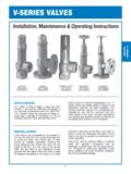
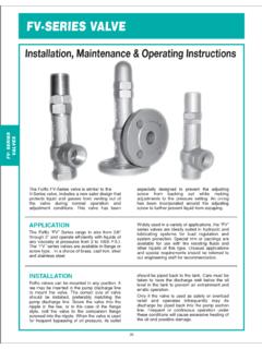
5 10V-SERIES VALVESA pplication and Installation .. 11 Valve Setting Maintenance Disassembly .. 12 Assembly Number Identification Chart .. 13 Standard Spring Pressure Range Chart .. 13 Dimensions and Parts List ..14-17VJ, VB, VS, VSS, VJ-SP ..14 VJF, VBF, VSF, VSSF, VJF-SP ..15 HVJ, HVB, HVS, HVSS ..16 HVJ-P, HVB-P, HVS-P, HVSS-P ..16 HVJF, HVBF, HVSF, HVSSF ..17 HVJF-P, HVBF-P, HVSF-P, HVSSF-P ..17 Performance Charts ..18-19 FV-SERIES VALVESA pplication and Installation .. 20 Valve Setting Maintenance Disassembly .. 21 Assembly Number Identification Chart .. 22 Standard Spring Pressure Range Chart .. 22 Dimensions and Parts List ..23-24 FVJ, FVB, FVS, FVSS ..23 FVJF, FVBF, FVSF, FVSSF ..24 Performance Charts ..25-26 OV-SERIES VALVESA pplication and Installation .. 27 Valve Setting Maintenance Disassembly .. 28 Assembly Number Identification Chart .. 29 Standard Spring Pressure Range Chart.
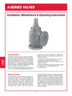
6 29 Dimensions and Parts List ..30-31 OVJ, OVB, OVS, OVSS ..30 OVJF, OVBF, OVSF, OVSSF ..31 Performance Charts ..32-33 A-SERIES VALVES Application and Installation .. 34 Valve Setting Maintenance Disassembly .. 35 Model Number and Ordering Information .. 36 Standard Spring Pressure Range Chart .. 36 Direct Acting Valves .. 37 Dimensions and Parts List ..37-38 AAD, ACD,ASSD..37 AADF, ACDF,ASSDF ..38 Performance Charts .. 39 Internal Pilot Operated Valves .. 40 Disassembly ..40 Dimensions and Parts List ..41-42 AAP, ACP, ASSP .. 41 AAPF, ACPF, ASSPF ..42 Performance Charts .. 43 SVB-SERIES VALVES (Underwriter Listed)Application and Installation .. 44 Maintenance Disassembly .. 45 Valve Setting .. 46 Model Number and Ordering Information .. 46 Standard Spring Pressure Range Chart .. 46 Dimensions and Parts List .. 47 Performance Charts .. 49-49 Notes .. 50 APPLICATIONST ypical Applications & Valve Definitions.
7 51 ENGINEERINGDATAV-SERIESVALVESFV-SERIESVA LVESA-SERIESVALVESSVBSERIESVALVESAPPLICA TIONSSPECIALTY VALVESOV-SERIESVALVESP lease contact FULFLO directly for special applications. We can engineer special or modified valves to meet your of Performance ChartsENGINEERINGDATAFULFLO GUIDED PISTON VALVESThe trademark FULFLO expresses the basic principlethat the relief valve must have flow capacity equal tothat of the pipe lines to which it is connected. Thesliding piston concept and internal design contours ofFULFLO valves provide unique flow and stabilitycharacteristics for reliable performance without valves are designed to operate reliably atpressures as low as 2 PSI and as high as 1000 FULFLO valve reduces velocities through all butthe controlling interface of the valve thereby minimizingsystem power ordinary direct acting relief valves, FULFLO guided piston valves are less responsive to transientpressure surges thereby eliminating the tendency topound, squeal or chatter.
8 Quiet, stable, effic ientperformance is assured in both load regulation andsystem protection valves operate ef fectively with all types ofliquids in the full range of viscosities including hydraulicoils, water, solvents and valves are not designed to be positive shut of f,and will pass a minimal amount of leakage before theset valves are NOTdesigned for use with air , gasor the FULFLO relief valve is a flow-modulatingdevice, pressure flow characteristics are completelydif ferent from spring loaded poppet or ball check types remain substantially tight up to crackingpressure. When this pressure is exceeded, the conventional valve pops open with a pressure drop atvery low flow and an exponential pressure rise as theflow contrast the FULFLO valve causes a pressure rise,over-pressure, as soon as flow starts; pressureincreases almost proportionally with flow. Springs andareas on FULFLO valves are carefully designed tominimize this pressures are important in sizing a valve.
9 Crackingpressuremust be selected high enough to permitsystem operation at its maximum rated pressure andflow. Over-pressureis limited by the system s capabilityto withstand the additional pressure and the motor sability to sustain the pump output at the increasedpressure for the required time over-pressure to produce a certain flow is afunction of valve size and spring constant and can bedetermined with the aid of the over-pressure chartsgiven for the different valve sizes. The valveperformance charts are based on tests made with oil of150 SSU viscosity at 100 F and may be used withreasonable accuracy within the conventional range ofoil viscosities from 30 to 500 SSU. For operation withhigh viscosity fluids, consult FULFLO s sizing a valve, the first attempt should be to select avalve equal in size to the pipe to which it is larger or smaller valve may be used to suit individualrequirements, depending on the permissible amount ofover-pressure.
10 Assume we have selected a 3/4 valvefor 17 GPM flow and a cracking pressure of 325 PSI. Byreferring to the pressure range chart, we find that wemay use either a YS or a ZS a YS spring, draw a line horizontally at 17 GPM in the 3/4 valve chart, to intersect the slanted linemarked YS and drop a vertical line to the over-pressure scale to read an over-pressure of 44 PSI. The17 GPM will be discharged at a pressure of 325 + 44 or369 PSI. The percentage of over-pressure would be44/325 X 100 or a ZS spring is used, extend the horizontal line to the ZS slope and the over-pressure is 70 PSU. Thepressure to pass 17 GPM would be 325 + 70 or 395 PSIand the over-pressure would be If the over-pressure is higher than desired for the particularapplication, the procedure may be repeated for the nextlarger size some cases, maximum flow through a valve at agiven pressure is specified.