Transcription of Fundamentals of Natural Gas Measurement - rmmsociety.org
1 Fundamentals ofNatural Gas Measurement | One Stop Solutionfor rotating and processing equipmentYour One Stop Solutionfor rotating and processing equipmentWhy Measure Natural Gas? Production Gathering Processing Purchase Sales Transportation Exchange Distribution Check Measurement System Physical Balance System Control Gas Storage System Capacity| One Stop Solutionfor rotating and processing equipmentYour One Stop Solutionfor rotating and processing equipmentOrifice Flow Measurement History 1797 Giovanni B. Venturi - First record use of orifices for the Measurement of fluids 1886 Clemons Herschel developed Modern Venturi Meter 1890 Professor Robinson of Ohio State University designed an orifice meter tomeasure gas 1903 Mr. Weymouth began a series of tests that lead to the publication ofcoefficients for orifice meters with flange taps 1924-1935 AGA & ASME conducted a great deal of research in developingcoefficient and standards of construction of orifice meters 1985 - First formal publication detailing the design and construction of orifice meters Joint effort of AGA & ASME - This report was the foundation of all subsequent last report to be published is AGA Report 3/API 2000.
2 Daniel Industry| One Stop Solutionfor rotating and processing equipmentYour One Stop Solutionfor rotating and processing equipmentTwo Basic Meter Types Linear Meters Turbine Rotary Diaphragm Ultrasonic Many Others Square Root Meters orifice Venturi Multi-Ported Averaging Pitot Wedge E-Quad-T V-Cone Many Others| One Stop Solutionfor rotating and processing equipment Most widely used method of flow measurementcurrently in use. Consists of a conduit and a restriction to create apressure drop. The conduit is normally pipe or tubing The restriction is normally a thin sharp edged orificeplate Meters are empirically calibrated Pass a known volume through the meter and recordthe pressure drop in order to provide a standard formeasuring other quantities Testing has been done in controlled labs to generatean empirical equationWhat is an orifice Meter?
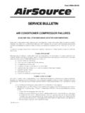
3 Meter TubeOrifice Plate| One Stop Solutionfor rotating and processing equipmentHow an orifice Meter Works As the fluid approaches the orifice the pressure increases slightlythen drops suddenly as the orifice is passed The decrease in pressure as the fluid passes thru the orifice is a result ofthe increased velocity of the gas passing thru the reduced area of theorifice| One Stop Solutionfor rotating and processing equipment Pressure continues to drop until the vena contracta is reachedand then gradually increases until 5 to 8 diameters downstream The vena contracta is the point of highest velocity & smallest crosssectional area All the pressure loss is not recovered because of friction (heat) loss andturbulence losses in the streamHow an orifice Meter Works| One Stop Solutionfor rotating and processing equipment The pressure drop increases when the rate of flow increases When there is no flow there is no differential The differential pressure is proportional to the square of the velocity,therefore the differential is proportional to the square of the rate offlowHow an orifice Meter Works| One Stop Solutionfor rotating and processing equipment AGA 2000 Report No.
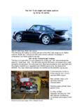
4 3 API orifice Plate Specifications Meter Tube Specifications ASME or ASME Tube Pressure Rating Tube Non-Destructive TestingMeter Tube Construction| One Stop Solutionfor rotating and processing equipmentOrifice Plate Specifications Plate is normally machined from a corrosive resistant material Important design Specifications/Considerations Plate Faces Plate Bore Edge Plate Bore Diameter and Roughness Bore Thickness Plate Thickness Plate Bevel Methods of securing the orifice plate in place orifice Flange Union Single-Chamber orifice Fitting Dual-Chamber orifice Fitting| One Stop Solutionfor rotating and processing equipmentMeter Tube Specifications orifice Fittings orifice Flange Union| One Stop Solutionfor rotating and processing equipmentMeter Tube Specifications orifice Fittings Single-Chamber orifice Fitting Dual-Chamber orifice FittingMAJOR MANUFACTURESDual ChamberSingle Chamber| One Stop Solutionfor rotating and processing equipmentMeter Tube Specifications Pipe Inside Surface RoughnessTolerance (250 micro-inchesor less) Internal Diameter Tolerance Upstream Required LengthPer AGA (44D for all beta andconfigurations) Downstream Required PerAGA (5D)
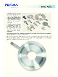
5 Threadolet/Coupling Taps End Connections5D44D| One Stop Solutionfor rotating and processing equipmentMeter Tube Specifications Flow Conditioning Used to improve flow conditions at the upstream faceof the orifice plate Straightening Vane Lengths Specified by AGA Reduces Swirl May not improve distorted flow5D| One Stop Solutionfor rotating and processing equipmentMeter Tube Specifications Flow Conditioning Flow Conditioner Lengths Specified byManufacturer s Testing Reduces Swirl Improves Distorted Flow| One Stop Solutionfor rotating and processing equipmentOrifice Plate Specifications Manufactured in two designconfigurations Paddle type Universal type Incorporates a precisely calculatedbore based on flowing and operatingconditions Hole is normally concentric aboutthe plate| One Stop Solutionfor rotating and processing equipmentInstallation Requirements orifice Plate Eccentricity Perpendicularity| One Stop Solutionfor rotating and processing equipment Meter Tube Length Meter Tube Internal Surface Finish Meter Tube Internal Diameter Pressure Tap Hole Location Pressure tap Hole Diameter orifice Plate Eccentricity orifice Plate Bypass TestOrifice Meter Tube Inspections| One Stop Solutionfor rotating and processing equipmentOther Meters Turbine Meters Typically used to measure fluid flow Rotary Meter Used to measure gas flow| One Stop Solutionfor rotating and processing equipmentYour One Stop Solutionfor rotating and processing equipmentQuestions or Suggestions