Transcription of The 964 Turbo engine and engine systems overview
1 The 964 Turbo engine and engine systems by Adrian Streather. 1991 911 (964) Turbo . Photo: Aldo Vannini The following information is a brief overview of the 964 Turbo engine and related systems . Hopefully it will provide 964 Turbo owners sufficient knowledge to understand how these systems operate. 964 series Turbocharged engines The first Turbo type 964-770 was released for model year 1991 and remained the same for model year 1992. The 964 Turbo had the 964 body and chassis structurally strengthened and given the wide body look. Mechanical systems were upgraded and the engine installed is an upgraded type 930/68 engine given the designationM30/69. The main differences between the 930/68 and the M30/69 engines are: Crankcase bolts similar to those used for the normally aspirated M64 engine . New cylinder design with optimised thermal characteristics. Stainless-steel cylinder head gasket (V2A).
2 Full-flow oil filter. Separate belt drive for 115A alternator/air conditioning compressor and engine driven fan. 930/XX turbocharged engine . Photo: Stephen Kaspar. Continuous injection system (K-Jetronic) with oxygen sensor control with a re-designed fuel distributor assembly. Three-way catalytic converter of metal construction. Optimised Turbo -charging system, including a larger intercooler assembly. Boost reduced to bar ( psi), down from bar ( psi) in the 930/68 Pressure-controlled transistorised ignition system (air pressure/ engine load input from the throttle body to a pressure sensor installed in ignition control unit) with digital spark control. The ignition system also introduced digital mapping for dwell and timing. In 1993 the litre turbocharged engine was replaced with a new litre variant. The new engine type M64/50 is a turbocharged version of the normally aspirated M64 engine main differences between theM30/69 and the M64/50 engines are:Crankcase is similar to the normally aspirated M64 versions.
3 Crankshaft, connecting rods, intermediate shaft and the oil pump are the same as the M64 series. Cylinder bore 100 mm. Vibration damper on crankshaft. 964 Turbo . Photo: Author's collection Stainless steel rings to provide cylinder head sealing. Cylinder heads similar to the normally aspirated M64 version. Exhaust valves are made of P25 and do not have a sodium filling. Chain drive housing the same as the normally aspirated M64 series. Camshaft and timing changed, exclusive to the M64/50 engine . The camshafts are made from high-grade chilled cast iron. Oil supply gallery similar to the normally aspirated M64 series. The oil passages plugged on the normally aspirated M64 series are opened for the M64/50 series. Top valve cover the same as the normally aspirated M64 series. Oil supply line to the turbocharger. Installation of a modified oxygen sensor control unit. Installation of a control pressure regulator with a higher hydraulic pressure at full load.
4 Installation of a modified throttle body. Installation of a modified and remapped Ignition control unit. Installation of a modified distributor. Note: Both the M30/69 and M64/50 turbocharged engines are designed to operate on 95 RON/ 85 MON fuels. However Porsche recommend that 98 RON fuel is used. Both turbocharged engine variants are not fitted with knock regulation protection. Continuous injection system (CIS, K-Jetronic) (turbocharged models) Introduction CIS used on the 964 engine is based on previous 911 Turbo systems . US MY1986-89911 Turbo owners will not notice much difference between their 930 Turbo engines and the new M30/69 engine . However owners from the rest of the world (RoW) will noticesome major differences in the Bosch continuous fuel injection system with oxygen sensor control and related sub- systems . Basic system operation Fuel Distributor The fuel distributor is made of aluminium and is fitted with a capsule valve.
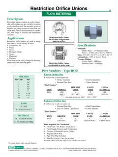
5 In order not to retard the over-spring effect during acceleration, a capsule valve now replaces the fixed orifice. This capsule valve opens as soon as the control plunger is lifted during acceleration. A fixed orifice is used to separate the lower chamber from system pressure. Pressure in the lower chamber may now be adjusted by the frequency valve controlling Fuel distributor and air flow sensor assembly. the flow to the return line. The port at the differential pressure valve, the differential pressure and, hence the quantity of fuel injected may be adapted accurately according to requirements. The fuel distributor is also fitted with a pressure balance valve. The purpose of this valve is to stop a vacuum build up in the control plunger area if the engine is switched off when it is hot. Fuel expands when it is heated up and if there is a build up of vacuum in the control plunger area, when the Turbo is next started it may run too rich.
6 The pressure balance valve is used to separate the volume above the control plunger and the return line. When the sustaining pressure drops below bar excess pressure, the pressure balance valve opens to prevent vacuum build up in this area. Note: In the 964 Turbo system the connector at the fuel distributor (sensor plate contact) is no longer used. The fuel pumps are controlled by an engine speed pulse from the ignition control unit. Air flow sensor. When the throttle valve opens, the air energy (PL) forces the sensor plate down and the control plunger is moved upwards. The fuel above the control plunger lifts the capsule valve flow is not directed past the orifice but is deviated around the valve. This allows the metering port to open faster to a greater degree. The pressure pulse inside the line leading to the control pressure regulator is absorbed by the flexible hose connected between the fuel distributor and control pressure regulator.
7 Schematic: Dr Ing. h. c. F. Porsche AG Continuous injection without oxygen sensor control On 964 turbos fitted with CIS injection without oxygen sensor control, the differential valves in the fuel distributor maintain the differential pressure at a constant level irrespective of the system pressure applied. The injection quantity can therefore only be influenced by the cross-section uncovered at the metering unit. The differential pressure between the upper and lower chamber is bar. The diaphragm is only deflected to the extent required by the fuel quantity injected. Continuous injection with oxygen sensor control (964 Turbo theory of operation). In order to adapt the fuel quantity injected to the desired fuel to air ratio at = 1, the pressure in the lower chambers of the fuel distributor is varied. if the pressure in the lower chamber is reduced the differential pressure at the metering ports is increased.
8 This in turn increases the fuel quantity that is injected. In order to vary the pressure inside the lower chambers, those chambers are separated from system pressure by a fixed restriction (as opposed to the standard CIS fuel distributor). Another restriction is provided to connect the lower chambers to the fuel return line. This restriction is of variable design: As long as the restriction remains open, pressure inside the lower chambers can drop. When closed the system pressure builds up inside the lower chambers. If this restriction is open and closed at a fast rate (pulsed), the pressure in the lower chamber may be varied according to the pulse-duty factor (ratio of closing time versus opening time). An electromagnetic valve (frequency valve) is used as a variable restriction device. It is controlled electrically by pulses emitted by the oxygen sensor control unit. The frequency valve is mounted in the fuel return line at the fuel distributor.
9 Frequency valve: The frequency valve is a L-Jetronic pulse fuel injector. The frequency valve is connected to the lower chambers of the fuel distributor and is fitted with a connection leading to the return line. The control units feed square pulses of a constant frequency (approx 70 Hr) but of variable pulse width, the frequency valve. This pulse width is referred to as the pulse-duty factor. In lean control means the pulse width or pulse-duty factor is below approximately 50%. In rich control means the pulse width or pulse-duty factor is above approximately 50%. A constant pulse-duty factor means operation without governing. If a pulse is present at the frequency valve, the needle valve opens to permit fuel flow to the return line. The result of this is that pressure in the lower chamber of the fuel distributor drops until the frequency valve is closed again. As a result of the relatively high frequency of the pulses a medium pressure level is obtained in the lower chamber.
10 Fuel supplied to the injectors is directly proportional to the pressure in the lower chamber. The higher the pressure in the lower chamber the less the fuel supplied to the injectors. The lower the pulse-duty factor, the less the pressure in the lower chamber is reduced and therefore less fuel is supplied to the injectors. Lean operation. The more the frequency valve is opened, the lower the pressure in the lower chamber and more fuel is supplied to the fuel injectors. Rich operation. Oxygen sensor control. The oxygen sensor control unit is mounted underneath the left hand seat. There are two different part numbers used for the litre engine , ROW 965 618 103 00 USA 965 618 103 01 The Turbo system uses a modified oxygen sensor control unit, which processes the 0 (idle) throttle switch position. This is done to improve pickup of the enginein the low load range. Oxygen sensor speed is only doubled if the throttle opening angle exceeds 7.