Transcription of FUZZY Based PID Controller for Speed Control of …
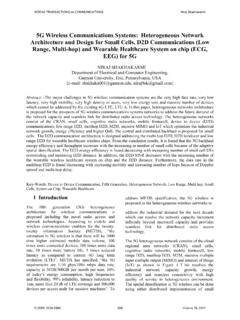
1 FUZZY Based PID Controller for Speed Control of Motor Using LabVIEW SALIM, JYOTI OHRI Department of Electrical Engineering National Institute of Technology Kurukshetra INDIA Abstract: - This paper presents an implementation of self-tuned PID Controller (FPID) for Speed Control of DC motor Based on LabVIEW (Laboratory Virtual Instrument Engineering Workbench Environment). The algorithms of FUZZY PID Controller (FPID) and conventional PID Controller (CPID) are implemented using PID and FUZZY Logic simulation toolkits of the Lab View environment. The simulation results demonstrate that the designed self-tuned PID Controller realize a perfect Speed tracking with lesser rise time and settling time, minimum steady state error and give better performance compared to conventional PID Controller .
2 Key-Words: - DC Motor, Ziegler-Nichols Tuning, Speed Control , FUZZY Logic and FUZZY plus PID Controller , LabVIEW. 1 Introduction Virtual instrumentation is the use of optimizable software and modular measurement hardware to aids in creating a user-defined measurement system, called virtual instruments. LabVIEW is a software package for high performance numerical computation and visualization. It is ideal for any measurement or Control system, and the heart of the NI (National Instruments) design platform. NI-LabVIEW provides comprehensive tool that is needed to build any measurement or Control application in dramatically lesser time, LabVIEW is the ideal development environment for innovation, discovery, and accelerated results [4][8].
3 In this paper, Speed of a DC motor is controlled using different tuning algorithms. The DC motors are popular in the industry Control area for a long time because they possess good characteristics, for example: high start torque characteristics, high response performance, easier to be linearly controlled etc. The basic property of DC motor is that Speed of DC motor can be adjusted by varying its terminal voltage. Therefore, the DC motor Control is better than other kinds of motors. The real-time application can be easily understood and interfaced with LabVIEW with a quick response but it may not be very apparent and easily comprehensive with MATLAB and other simulation software.
4 In the present work, PID Controller is used to Control the Speed of the DC motor. 2 DC Motor Mathematical Model DC motor system is a separately excited DC motor, which is often used to the velocity tuning and the position adjustment [3] [10].The equivalent circuit of the DC motor using the armature voltage Control method is shown in : : Equivalent circuit of the DC motor. Where : Armature resistance ( ) : Armature inductance (H) : Armature current (A) : Field current (A) : Input voltage (V) : Back electromotive force (EMF) (V) : Motor torque (Nm) : An angular velocity of rotor (rad/s) J : Rotor inertia (kgm ) B : Friction constant (Nms/rad) : EMF constant (Vs/rad) : Torque constant (Nm/A) WSEAS TRANSACTIONS on SYSTEMS and CONTROLS alim, Jyoti OhriE-ISSN: 2224-2856154 Volume 10, 2015 The functional block diagram of a DC motor armature voltage Control system is shown in : Fig.
5 2: DC motor armature Control system block diagram. The transfer function of DC motor Speed with respect to the input voltage can be written as follows, (1) A LabVIEW Based DC motor model was built in order to run FUZZY and PID algorithms and also to analyze their works. 3 Tuning Methods Speed of DC motor can be controlled using different tuning methods and are as follows:- I. PID Controller (Ziegler- Nichols Method) II. FUZZY Controller III. PID Plus FUZZY Controller PID Controller (Ziegler- Nichols Method) The development of PID Control theories has already started in early sixties. PID Control has been one of the Control system design methods of the longest history.
6 PID Controller is mainly to adjust an appropriate proportional gain ( ), integral gain ( !), and differential gain ( ") to achieve the optimal Control performance [4][6]. The relationship between the input e(t) and output u(t) can be formulated in the following, U t K&e t (K)*e t dt,-( , /, (2) A general PID Controller system block diagram is shown in : Fig. 3: PID Controller system block diagram. The transfer function is expressed as follows, C s K&(345( 6 5 7 5 (3) PID controllers are tuned in terms of , ! and ". Ziegler- Nichols is a type of continuous cycling method for Controller tuning. The term continuous cycling refers to a continuous oscillation with constant amplitude and is Based on the trial-and-error procedure of changing the proportional gain ( ).)))
7 Is increased from small value till the point at which the system goes to unstable. Thus the gain at which system starts oscillating is noted as the ultimate gain ( 9) and period of oscillations is the ultimate time period (:9). These two parameters, 9 and :9 are used to find the loop-tuning constants of the PID Controller using the formula tabulated in [3] [8] for Ziegler Nichols parameters The advantage of this method is that it is a proven online method and includes dynamics of whole process, which gives a more accurate picture of how the system is behaving. FUZZY Controller Design FUZZY Logic (FL) incorporates a simple, rule- Based IF X AND Y THEN Z approach to a solving Control problem rather than attempting to model a system mathematically.
8 FUZZY logic provides an alternative way to represent linguistic and subjective attributes of the real world in computing. FL requires some numerical parameters in order to operate such as what is considered significant error and significant rate-of-change-of-error, but exact values of these numbers are usually not critical unless very responsive performance is required in which case empirical tuning would determine them.[7] [10] Controller ;< ;= ;> P 9 0 PI 9 0 PID 9 :92 :98 WSEAS TRANSACTIONS on SYSTEMS and CONTROLS alim, Jyoti OhriE-ISSN: 2224-2856155 Volume 10, 2015 FUZZY Controller process block is shown in : : Process Blocks for a FUZZY Controller . Basically, FLC process is Based on experiences and linguistic definitions instead of system model.
9 The input to the FUZZY Controller are error e(t) and Change of error de(t). e(t) = R(t) U(t) (4) de(t) = e(t) e(t-1) (5) Using FUZZY Control rules Speed of DC motor can be controlled. Block diagram for Speed Control of DC motor using FUZZY Controller is shown in : : Speed Control of DC motor using FUZZY Controller . FUZZY membership function using triangular and trapezoidal functions for Speed of error is shown in Fig 6; for Speed of change of error is shown in Fig 7; and for output signal is shown in Fig 8. : Membership Function for error signal. : Membership Function for change of error signal. : Membership Function for output signal.
10 Based on Speed of error, change of error, output signal and some defined set of rules we have input output relationship for FUZZY Controller as shown in Fig 9. Here U(t) is output signal, e(t) is Speed of error and Ce(t) is change of Speed of error. : Input and output relationship for FUZZY Controller . PID Plus FUZZY Controller Design FUZZY plus PID (FPID) provides good performance as compared to standalone FUZZY . Simple rule base are used for FUZZY Controller while FPID uses different rule base for proportional, integral and derivative gains to make response faster [12]. The input to the Self-tuning FUZZY PID Controller are error e(t) and Change of error de(t) as given in and in Using FUZZY Control rules on-line, PID parameters , !