Transcription of G761 Series Servovalves ISO 10372 Size 04 - kostek
1 G761 Series ServovalvesISO 10372 size 04 The actual flow is dependentupon electrical command signaland valve pressure for a given valve pressuredrop can be calculated usingthe square root function forsharp edge orifices: pQ = QN pNQ gpm[l/min] = calculated flowQNgpm[l/min] = rated flow p psi[bar] = actual valvepressure drop pNpsi[bar] = rated valvepressure dropG761 Series SERVOVALVESThe G761 Series flow controlservovalves are throttle valvesfor 3- and preferably are a highperformance, two-stage designthat covers the range of ratedflows from 1 to gpm at1000 psi valve output stage is a closed center,four-way, sliding pilotstage is a symmetrical double-nozzle and flapper, driven by adouble air gap, dry torquemotor.
2 Mechanical feedback ofthe spool position is providedby a cantilever valvedesign is simple and rugged fordependable, long life valves are suitable forelectrohydraulic position,speed, pressure or force con-trol systems with high dynamicresponse of operationAn electrical command signal(flow rate set point) is appliedto the torque motor coils andcreates a magnetic force, whichacts on the ends of the pilotstage causes adeflection of armature/flapperassembly within the flexuretube. Deflection of the flapperrestricts fluid flow through onenozzle, which is carried throughto one spool end, displacingthe of the spool opensthe supply pressure port (P) toone control port while simulta-neously opening the tank port(T)
3 To the other control spool motion also appliesa force to the cantilever spring,creating a restoring torque onthe armature/flapper the restoring torquebecomes equal to the torquefrom the magnetic forces, thearmature/flapper assemblymoves back to the neutralposition, and the spool is heldopen in a state of equilibriumuntil the command signalchanges to a new summary, the spool positionis proportional to the constant pressuredrop across the valve, flow tothe load is proportional to thespool FEATURES 2-stage design with dry torque motor Low friction double nozzle pilot stage High spool control forces High dynamics Rugged, long-life design High resolution, low hysteresis Completely set-up at the factory Optional fifth port for separate pilot supply Field replaceable first stage disc filterG761 SERIESTWO STAGE SERVOVALVESThis catalog is for users with ensure that all necessarycharacteristics for function and safetyof the system are given, the user hasto check the suitability of the products described here.
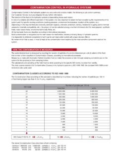
4 In case of doubt, please contact Moog Pressure*ports P, X, A and Bup to 4,500 psi [315 bar]port Tup to 3,000 psi [210 bar]Temperature RangeFluid-20 to 275 F [-29 to 135 C]Ambient-20 to 275 F [-29 to 135 C]Seal Material**Fluorocarbon (Viton)Operating FluidCompatible with common hydraulic fluids, other fluidson viscosity60 450 SUS @ 100 FSystem Filtration:High pressure filter (without bypass,but with dirt alarm) mounted in the main flow and, ifpossible, directly upstream of the valve. Refer to Moogfiltration catalog for recommended filtration of Cleanliness:The cleanliness of the hydraulic fluid greatly effects the performance (spool positioning, highresolution) and wear (metering edges, pressure gain, leakage) of the Cleanliness ClassFor normal operationISO 4406 < 14/11 For longer lifeISO 4406 < 13/10 Filter RatingrecommendedFor normal operation 10 75 (10 m absolute)For longer life 5 75 (5 m absolute)Installation OperationsAny position, fixed or g, 3 lb ( lb for steel body)Degree of ProtectionEN50529P.
5 Class IP65, with mating connector PlateDelivered with an oil sealed shipping Rate Q (gpm)Valve Pressure Drop p (psi) 3000 gpm [19 lpm] gpm [38 lpm] gpm [63 lpm] gpm [10 lpm] gpm [4 lpm]G761-3003G761-3004G761-3002G761-3001 G761-3005 Valve Flow DiagramValve flow for maximum valve opening (100% command signal) as a function of the valve pressure drop.* Maximum special order is 8,000 psi [550 bar]** Other seal material upon requestG761 SERIESGENERAL TECHNICAL DATAPA T BX42-4-8-100-2-6101001000 Amplitude Ratio (dB)Frequency (Hz)Frequency Response of1, , 5 gpm Servovalves12 010 0806040200 Phase Lag ( ) 40% 100%2-4-8-100-2-6101001000 Amplitude Ratio (dB)Frequency (Hz)Frequency Response of10 gpm Servovalves12 010 0806040200 Phase Lag ( )
6 40% 100%120100806040200 Time milliseconds36 912150 Control Flow % rated123231, , 5 gpm10 gpm15 gpm1 Frequency Response* Typical response charateristics for G761 Series Response* Typical transient response of G761 Series PatternISO 10372 - 04 - 04 - 0 - 92 Valve Body Version4-way2-stage with spool bushing assemblyPilot StageNozzle/FlapperPilot ConnectionOptional, Internal or ExternalFluid SupplyG761 Series Servovalves are intendedto operate with constant supply pressureSupply PressureMinimum200 psi [14 bar]Maximum Standard4,500 psi [315 bar]Proof Pressureat P Port6,750 psi [473 bar]at T Port4,500 psi [315 bar]Rated Flow Tolerance@ 1,000 psi PN[%] 10 Symmetry[%]< 10 Threshold*[%]< *[%]< Shiftwith Temp.
7 , 100 F [55 K] variation[%]< acceleration to 10 g< every 1,000 psi [70 bar] supply pressure change< return pressure 0 to 500 psi [0 to 35 bar]< Ratio (dB)Frequency (Hz)Frequency Response of15 gpm Servovalves12 010 0806040200 Phase Lag ( ) 40% 100%* Measured at 3,000 psi pilot or operating pressureNOTE: High response is available, consult factoryG761 SERIESTECHNICAL DATAG761-3001, 3002, 3003G761-3004G761-3005 XYF4 ATBXF2 GPF3F15 PIN [ ]EXTERNAL NULL [ ] COVERPIN [ ]3/32 IN. HEX [ ][ ]CONNECTORPIN CP PORTS tandard electrical connector mates withMS3106F14S-2 Sor mounting manifoldmust conform to ISO to which valve ismounted requires a 32[ ] finish, flat within [ ] external null adjust:flow out of port B will increasewith clockwise rotation of nulladjust (3/32 hex key).
8 Flow bias is continually variedfor a given port as the nulladjust is SERIESINSTALLATION DRAWINGSCONVERSION INSTRUCTION For operation with internal or external pilot B T X GF1F2F3F4 .32 .32 .32 .32 .2 .145/16-185/16-185/16-185 B T X GF1F2F3F4 5 *The standard version of these valves is configured as internal pilot pilot supply configuration requires model number flowScrew & Seal Washer Location (M4 X 6 DIN EN ISO 4762)supplyXPInternal P*closedopenExternal XopenclosedRated current andcoil resistance A variety of coils areavailable for G761 Series connectionsA four-pin electrical box connector (that mates withan MS3106F14S2S cableconnector)
9 Is four torque motor leadsare available at the connectorso external connections canbe made for Series , parallelor single coil servoamplifier respondsto input current, so aservoamplifier that hashigh internal impedance(as obtained with currentfeedback) should be will reduce the effectsof coil inductance and willminimize changes due tocoil resistance Resistance[ ]Rated Current[mA]Coil Inductance @ 50 Hz[H]Electrical Power[W]Polarity for Valve OpeningP B, A TParallel40 and C (+) B and D (-)Series160 (+), D (-)Single80 (+), B (-)or C (+), D (-)ABCDABCDABCDNote.
10 Before applying electrical signals the pilot stage has to be SERIESELECTRICAL CONNECTIONS(Examples with typical G761 Series coils)7 Moog PartSizeMoog Part NumberFPM 85 Shore O-Rings (included in delivery),for P,T, A and BID x [ x ]42082-022for XID x [ x ]42082-013 Mating Connector, waterproof IP 65 (not included in delivery)49054F14S2S(MS3106F14S-2S)Flush ing Block (not included in delivery)55124 Moog PartSizeMoog Part Number Mounting Bolts (not included in delivery)(4 pieces)5/16 - 18 NC x 1-3/4 longA31324-228B[ x 45 mm long][B64929-8B45]Field Replaceable Filter Kit (includes service manual)B52555RK201K1 Pilot Supply ScrewM4 x 6 DIN EN ISO 476266098-040-006 Seal for Set ScrewA25528-040 SPARE PARTS AND ACCESSORIESG761 SERIESORDERING INFORMATIONSPARE PARTS AND ACCESSORIESG761 Optional FeatureSeries specificationModel NumberType Designation J GM VP Model DesignationAssigned at the factoryFactory Identification (Revision Level)