Transcription of 771,772,773 Series Servovalves - Moog Inc.
1 771, 772, 773 Series Servovalves 771/2/3 Series . TWO STAGE Servovalves . 771/2/3 Series Servovalves a cantilever valve deflection of the armature/flap- Once the restoring torque design is simple and rugged for per assembly within the flexure becomes equal to the torque The 771/2/3 Series flow con- dependable, long life operation. tube. Deflection of the flapper from the magnetic forces, the trol Servovalves are throttle These valves are suitable restricts fluid flow through one armature/flapper assembly valves for 3- and preferably for electrohydraulic position, nozzle which is carried through moves back to the neutral 4-way are a speed, pressure or force con- to one spool end, displacing position and the spool is held high performance, two-stage trol systems with high dynamic the spool. open in a state of equilibrium design that covers the range of response requirements. Movement of the spool until the command signal rated flows from 1 to 15 gpm opens the supply pressure port changes to a new level.
2 At 1000 psi valve (P) to one control port, while In summary, the spool output stage is a closed center, An electrical command signal simultaneously opening the position is proportional to the Principle of operation four-way sliding pilot (flow rate set point) is applied tank port (T) to the other input current and with con- stage is a symmetrical double- to the torque motor coils, and control spool motion stant pressure drop across the nozzle and flapper, driven by creates a magnetic force which also applies a force to the valve, flow to the load is pro- a double air gap, dry torque acts on the ends of the pilot cantilever spring, creating a portional to the spool position. motor. Mechanical feedback of stage causes a restoring torque on the spool position is provided by armature/flapper assembly. VALVE FEATURES. 2-stage design with dry torque motor Rugged, long-life design Low friction double nozzle pilot stage High resolution, low hysteresis High spool control forces Completely set-up at the factory High dynamics Small body size The actual flow is dependent p upon electrical command signal Q = QN.
3 PN. and valve pressure flow for a given valve pressure drop can be calculated using Q [gpm] = calculated flow the square root function for QN [gpm] = rated flow sharp edge orifices: p [psi] = actual valve pressure drop pN [psi] = rated valve pressure drop This catalog is for users with technical system are given, the user has to check the Intrinsically safe valve versions are available for use in hazardous locations. ensure that all necessary suitability of the products described here. Specific models are certified to FM,ATEX, CSA, and TIIS standards. Contact the factory characteristics for function and safety of the In case of doubt, please contact Moog Inc. for details. 2. 771/2/3 Series . GENERAL TECHNICAL DATA. Operating Pressure ports P,T,A and B up to 3,000 psi Flow Rate Q (gpm). Temperature Range Fluid -40 to 275 F. Ambient -40 to 275 F Seal Material Viton others on request Operating Fluid Compatible with common hydraulic fluids, other fluids on request.
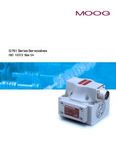
4 Pm Recommended viscosity 60-450 SUS @ 100 F 0g 15. System Filtration: High pressure filter (without bypass, pm but with dirt alarm) mounted in the main flow and if possible, 0g 10. directly upstream of the valve. Class of Cleanliness: The cleanliness of the hydraulic fluid greatly effects the performance (spool positioning, high resolution) gpm and wear (metering edges, pressure gain, leakage) of the servovalve. Recommended Cleanliness Class For normal operation ISO 4406 < 14/11. For longer life ISO 4406 < 13/10 gpm Filter Rating recommended For normal operation 10 75 (10 m absolute) For longer life 5 75 (5 m absolute). Any position, fixed or moveable. gpm Installation Operations Vibration 30 g, 3 axes Weight lb [.09 kg]. EN50529P: class IP65, with .05. 200 300 400 500 700 1000 2000 3000. Degree of Protection mating connector mounted. Valve Pressure Drop p (psi). Delivered with an oil sealed shipping plate. Shipping Plate Valve flow for maximum valve opening (100% command Valve Flow Diagram signal) as a function of the valve pressure drop.
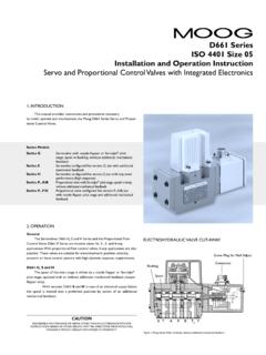
5 P B T A. View from Pressure Side 3. 771/2/3 Series . TECHNICAL DATA. Model Type 771 771 773. Mounting Pattern ISO 10372 - 02 - 02 - 0 - 92. Valve Body Version 4-way 2-stage with spool bushing assembly Pilot Stage Nozzle/Flapper, Highflow Pilot Connection Optional, Internal or External Internal only Rated Flow ( 10%) at p = 1,000 psi N. Standard [gpm] Response Time* Standard [ms] 6 6 6 10 16. Threshold* [%] < Hysteresis* [%] < Null Shift at T = 100 F [%] < Null Leakage Flow* max. [gpm] * Measured at 1,000 psi pilot or operating pressure curves with 40% and 100%. Typical characteristic 771 Series 772 Series 773 Series +2 +2 +2. input signal, measured at Amplitude Ratio (dB). Amplitude Ratio (dB). Amplitude Ratio (dB). 0 0 0. 3,000 psi operating pressure. -2 -2 -2. -4 -4 -4. 3000 psi DTE-24. -6 at 100 F (38 C) 120 -6 3000 psi DTE-24 120 -6 120. Rated Current: at 100 F (38 C). -8 100 -8 Rated Current: 100 -8 3000 psi DTE-24 100.
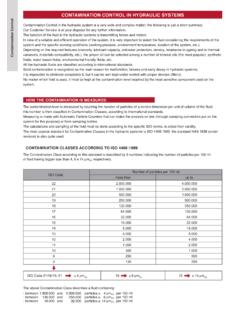
6 40% at 100 F (38 C). Phase Lag (degrees). Phase Lag (degrees). Phase Lag (degrees). -10 100% 80 -10 40% 80 -10 Rated Current: 80. 100%. 60 60. 40%. 100% 60. 40 40 40. 20 20 20. 10 20 30 50 70 100 200 300 500 1000 10 20 30 50 70 100 200 300 500 1000 10 20 30 50 70 100 200 300 500 1000. Frequency (Hz) Frequency (Hz) Frequency (Hz). Frequency Response Frequency Response Frequency Response of 1, , and 5 gpm Servovalves of 10 gpm Servovalves of 15 gpm Servovalves 4. 771/2/3 Series . INSTALLATION DRAWINGS. [ ] [ ] 4X .221 [ ] THRU..014 M. MAX [ ] OR. [ ] 4X .265 [ ] THRU. (OPTION) .007 M. [ ]. MAX. [ ] [ ]. [ ]. [ ]..671..844 [ ]. [ ]. [ ]. PIN D PIN A ELECTRICAL CONNECTOR [ ]. PIN C PIN B. [ ]. [ ] [ ]. [ ] MTG HGT. [ ]. P. LOCATING PIN .062 .12 MAX. [ ] [ ]. EXTERNAL NULL ADJUST. 3/32 IN. HEX. SOCKET. TYPICAL SUBPLATE MANIFOLD The mounting manifold must conform to C VALVE MOUNTING. Surface to which valve is ISO 10372-03-03-0-92.
7 007 M RETURN PORT T. 4 HOLES ( ) A PORT CIRCLE mounted requires a 32 [ ]. CONTROL PORT B .844. ( ). finish, flat within [ ] TIR. 2X .62. CONTROL PORT A. Flow out of Port B will increase For External Null Adjust: .672. with clockwise rotation of null ( ) adjust screw (3/32 hex key). ( )..500. Flow bias is continually varied For External Null Adjust: for a given port as the null 2. adjust is rotated. B PORT DIA VALVE MOUNTS ON. THIS MANIFOLD SURFACE..010 M .390. 4 HOLES .156 .20..026 M. 4X PORT PER SAE J1926..750-16 UNF-2B DASH 8. STR THD O-RING BOSS. PRESSURE PORT P. (.50 TUBE OD REF) 32..002. 4X .344 THRU..531 .48 PRESSURE. 2X .62..013 M. TYPICAL SUBPLATE MANIFOLD. Model A Port B Port C Mtg Number Circle Dia Dia Holes 771-XXX .625 .191 .190-32 NF. 772-XXX .780 .261 .190-32 NF. 773-XXX .937 .312 .250-20 NC. 5. 771/2/3 Series . ELECTRICAL CONNECTIONS. A four-pin electrical con- The servovalve responds Rated current and Coil connections Servoamplifier A variety of coils are available nector (that mates with an to input current, therefore, coil resistance for 771/2/3 Series Servovalves , MS3106F14S-2S) is standard.
8 A servoamplifier that has which offer a wide choice of All four torque motor leads high internal impedance rated current. See Table 1. are available at the connector (as obtained with current so external connections can feedback) should be used. be made for Series , parallel This will reduce the effects or differential operation. of coil inductance and will 771/2/3 Series Servovalves minimize changes due to can be supplied on special coil resistance variations. order with other connectors or a pigtail. ELECTRICAL Parallel Series Single CONNECTIONS. (Examples with typical 771/2/3 Series coils) A B C D A B C D A B C D. Coil Resistance [ ] 100 400 200. Rated Current [mA] 15 15. Electrical Power [W] .023 .023 .045. Connections for Valve Opening A and C (+) A (+), D (-) A (+), B (-). P B, A T B and D (-) B and C connected or C (+), D (-). Note: Before applying electrical signals the pilot stage has to be pressurized. TABLE 1.
9 Nominal Recommended Rated Current mA Approximate Coil Inductance* Henrys Resistance Per Coil at Parallel, 77 F (25 C) Differential or Single Series Coils Single Coils Series Coils Parallel Coils Coil Operation 80 40 20 200 15 1000 8 4 * Measured at 50 Hz 6. 771/2/3 Series . ORDERING INFORMATION. SPARE PARTS AND ACCESSORIES. Model Number Type Designation 771, 772, 773 . Signals for 100% Spool Stroke 4 mA Series Optional Feature Series specification 4. Intrinsically safe H mA Series 20 mA Series K. L. N 30 mA Series 100 mA Series Model Designation Assigned at the factory Z. Y Special signal (see spec. sheet). Factory Identification (Revision Level) Valve Connector A Connector C1 (A) side (RH). Valve Version B Connector C2 (B) side (LH). S Standard response X Special connector Rated Flow Seal Material QN[gpm] at pN = 1,000 psi V Fluorocarbon Standard High Response N NBR (Buna). 04 1 771 Series only Others on request 10 771 Series only 19 772 Series only 772 Series only Pilot Connections and Pressure Pressure [psi] Supply 38.
10 773 Series only 250 to 3,000 internal 57. A. Maximum Operating Pressure pp and Body Material 3,000 psi aluminum Spool Position without Electrical Signal M Mid position F. Main Spool Type 4-way / axis cut / linear Pilot Stage F Standard dynamics O. D 4-way / +/-10% overlap / linear X Special Preferred configurations highlighted. All combinations may not be available. Options may increase price and delivery. Technical changes are reserved. SPARE PARTS AND ACCESSORIES. O-Rings (included in delivery), for P,T, A and B FPM 85 Shore Moog P/N. 771 ID x 42082-007. 772 ID x 42082-013. 773 ID x 42082-022. Mating Connector, waterproof IP 65 (not included in delivery) 49054F14S2S (MS3106F14S-2S). Flushing Block 771 and 772 A01704-1K1. 773 A01704-2K1. Mounting Bolts (included in delivery). 771 and 772 .190-32 NF x long (4 pcs.) C39674-132. 773 .250-20 NC x long (4 pcs.) A31324-136Z. Field Replaceable Filter Kit B52555RK54K1. 7.