Transcription of PILOT OPERATED FLOW CONTROL VALVE WITH …
1 HIGH PERFORMANCE, TWO-STAGE DESIGN PROVIDING FLOW CONTROL IN A SIMPLE, DEPENDABLE, LONG-LIFE DESIGNWHAT MOVES YOUR WORLDRev. V, June 2018 SERVO valves PILOT OPERATEDFLOW CONTROL VALVEWITH ANALOG INTERFACE72 SERIESISO 10372-06-05-0-92 Moog 72 Series Flow CONTROL Servo ValvesINTRODUCTION2 Whenever the highest levels of motion CONTROL performance and design flexibility are required, you ll find Moog expertise at work. Through collaboration, creativity and world-class technological solutions, we help you overcome your toughest engineering obstacles. Enhance your machine s performance. And help take your thinking further than you ever thought Product Overview 3 Features and Benefits 4 Description of Operation 5 TECHNICAL DATA General, Hydraulic, Static and Dynamic 6 Response Curves 7 Electrical Data 8 Installation Drawings and Null Adjust Instructions 9 Hole Pattern for Mounting Surface 10 BACKGROUND Null Flow Adjustment 11 Flow Calculation and Null Cut Options 12 Related Products 13 Routine Maintenance Guidelines 14 About Moog 15 ORDERING INFORMATION Accessories and Spare Parts 17 Ordering Code 18 This catalog is for users with technical knowledge.
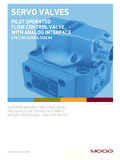
2 To ensure all necessary characteristics for function and safety of the system, the user has to check the suitability of the products described herein. The products described herein are subject to change without notice. In case of doubt, please contact Moog. Moog is a registered trademark of Moog Inc. and its subsidiaries. All trademarks as indicated herein are the property of Moog Inc. and its subsidiaries. For the full disclaimer refer to the most current information, visit or contact your local Moog V, June, 2018 TABLE OF CONTENTSPRODUCT OVERVIEWThe 72 Series flow CONTROL servo valves are throttle valves for 3 and preferably 4-way applications. They are a high performance, 2-stage design that covers the range of rated flows from 95 to 225 l/min (25 to 60 gpm) at 35 bar (500 psi) VALVE pressure drop per spool land. The output stage is a closed center, four-way sliding spool. The PILOT stage is a symmetrical double-nozzle and flapper, driven by a double air gap, dry torque motor.
3 Mechanical feedback of spool position is pro vid ed by a cantilever spring. The VALVE design is simple and rugged for de pendable, long life op era tion. These valves are suitable for electrohydraulic position, speed, pressure or force CONTROL systems with high dynamic response 72 Series is ideally suited for applications in the 95 to 225 l/min (25 to 60 gpm) when superior dynamics are a safe VALVE versions are available for use in applications with potentially hazardous environments. Specific models are certified to FM, ATEX, CSA, TIIS and IECEx 72 Series Flow CONTROL Servo ValvesINTRODUCTIONTIISI ntrinsically safe VALVE versions are available for use in potentially hazardous environments. Specific models are certified to FM, ATEX, CSA TIIS and IECEx standards. Contact Moog for design 2-stage, with spool and bushing and dry torque motorMounting surface ISO 10372-06-05-0-92 Rated flow at pN 35 bar/spool land 95 l/min 150 l/min 225 l/min(500 psi/spool land) (25 gpm) (40 gpm) (60 gpm)Maximum operating pressure to ports P, T, A, B, X 210 bar (3,000 psi) PILOT Design Nozzle FlapperStep response time for 0 to 100% stroke 11 ms 18 ms 33 ms3 Rev.
4 V, June, 2018 Features Benefits2-stage design Enables high machine performance, faster cycle times and greater accuracy - all resulting in higher productivity100% factory tested to ensure critical specification Ensures smooth and easy startup, reduces downtime and performance insures long life in critical industrial applicationsDual Coil torque motor Redundancy for high reliabilityDual Precision Nozzles in Torque Motor Precision flow CONTROL and predictabilityDry torque motor design Eliminates potential contamination issues in the air gaps of the torque motor that could cause machine downtimeHardened 440C Bushing and Spool Provides for long life, wear resistance when used in the harsh environments; provides for low sliding friction during useEmergency failsafe positioning Most valves are set up to return to a failsafe position when the command signal is interrupted or eliminatedField replaceable PILOT stage filter Enables preventive maintenance in the field, saving precious machine downtime and service costsExternal null bias adjustment Enables technicians to manually adjust the null bias of the VALVE to adapt to the conditions of the machine (see section on null flow adjustment Page 12).
5 This feature provides a simple adjustment to machine performance without the need to adjust a AND BENEFITSThe 72 Series is part of Moog s family of Mechanical Feedback Servo valves . This is proven technology that performs reliably in machines where high performance, stability and accuracy are required. Moog s Mechanical Feedback valves are designed to provide high reliability and long service life. Moog 72 Series Flow CONTROL Servo ValvesINTRODUCTION4 Rev. V, June, 2018 DESCRIPTION OF OPERATIONThe 72 Series Flow CONTROL Servo VALVE consists of a polarized electrical torque motor and two stages of hydraulic power amplification. The motor armature extends into the air gaps of the magnetic flux circuit and is supported in this position by a flexure tube. The flexure tube acts as a seal between the electromagnetic and hydraulic sections of the VALVE . The 2 motor coils surround the armature, one on each side of the flexure flapper of the first stage hydraulic amplifier is rigidly attached to the midpoint of the armature.
6 The flapper extends through the flexure tube and passes between 2 nozzles, creating two variable orifices between the nozzle tips and the flapper. The pressure controlled by the flapper and nozzle variable orifice is fed to the end areas of the second stage spool. The second stage is a conventional four-way spool design in which output flow from the VALVE , at a fixed VALVE pressure drop, is proportional to spool displacement from the null position. A cantilevered feedback spring is fixed to the flapper and engages a slot at the center of the spool. Displacement of the spool defects the feedback sprint which creates a force on the armature/flapper signals induce a magnetic charge in the armature and cause a deflection of the armature and flapper. This assembly pivots about the flexure tube and increases the size of one nozzle orifice and decreases the size of the differential pressure created by this action causes spool motion.
7 The resulting spool displacement induces a linear force in the feedback wire which opposes the original input signal torque. Spool movement continues until the feedback wire force equals the input signal 72 Series Flow CONTROL Servo ValvesINTRODUCTION5 Rev. V, June, 2018 PBTAS poolInlet OrificeCoilBushingConnectorFeedback WireMagnet (not shown)Upper PolepieceFlexure TubeArmatureLower PolepieceFlapperNozzlesElectro-hydraulic Servo VALVE Cut-away Rated flow tolerance 10%Step response time for 0 to 100% stroke 95 l/min (20 gpm) = 11ms 150 l/min (40 gpm) = 18 ms 225 l/min (60 gpm) = 33 msThreshold < < shift for T = 38 C (100 F) < 72 SERIES SERVO VALVESMoog 72 Series Flow CONTROL Servo ValvesTECHNICAL DATA6 Rev. V, June, 2018 General Technical Data VALVE design 2-stage, with spool and bushing and dry torque motorPilot stage Nozzle Flapper Standard DynamicsMounting pattern ISO 10372-06-05-0-92 Installation position Any orientation, fixed or movableWeight kg ( lb)Storage temperature range -40 to +60 C (-40 to +140 F)Ambient temperature range -40 to +135 C (-40 to +275 F)Vibration resistance 30 g, 3 axis, 10 Hz to 2 kHzShock resistance 30 g, 3 axisSeal material Fluorocarbon (FKM) 85 SHORE Others upon requestHydraulic Data Maximum operating pressure to ports P, T, A, B 210 bar (3,000 psi) - - - 350 bar (5,000 psi) specialRated flow at pN 35 bar/spool land (500 psi/spool land) 95 l/min (25 gpm) 150 l/min (40 gpm) 225 l/min (60 gpm)Null adjust authority Greater than 10% of rated flowHydraulic fluid Hydraulic oil per DIN 51524 parts 1 to 3 and ISO 11158.
8 Other fluids on request. Temperature range -40 to +135 C (-40 to +275 F) Recommended viscosity range 10 to 85 mm2/s (cSt) Maximum permissible viscosity range 5 to 1,250 mm2/s (cSt)Recommended filter rating For functional safety 10 75 (10 m absolute) For longer life 5 75 (5 m absolute)Static and Dynamic Data (at 3,000 psi)72 SERIES SERVO valves Moog 72 Series Flow CONTROL Servo ValvesTECHNICAL DATA7 Rev. V, June, 20180204060801001220301040 Stroke (% of Rated Signal)Time (ms)0122030104020406080100 Time (ms)Stroke (% of Rated Signal)12020301040 Time (ms)20406080100 Stroke (% of Rated Signal)96 l/min (25 gpm)Plot 1 @ 210 bar (3,000 psi)Plot 2 @ 70 bar (1,000 psi)154 l/min (40 gpm)Plot 1 @ 210 bar (3,000 psi)Plot 2 @ 70 bar (1,000 psi)231 l/min (60 gpm)Plot 1 @ 210 bar (3,000 psi)Plot 2 @ 70 bar (1,000 psi)-2+2-4-8-10-608060100204072050200100 103015 Amplitude Ratio (Decibels)1243 Frequency (Hz)Phase Lag (Degrees)96 l/min (25 gpm)Plot 1 & 3 = 40% rated signal (solid)Plot 2 & 4 = 100% rated signal (dash)7205020010010301580601002040-2+2-4 -8-10-601243 Frequency (Hz)Phase Lag (Degrees)Amplitude Ratio (Decibels)72050200100103015-2+2-4-8-10-6 0806010020401243 Frequency (Hz)Amplitude Ratio (Decibels)Phase Lag (Degrees)154 l/min (40 gpm)Plot 1 & 3 = 40% rated signal (solid)Plot 2 & 4 = 100% rated signal (dash)
9 231 l/min (60 gpm)Plot 1 & 3 = 40% rated signal (solid)Plot 2 & 4 = 100% rated signal (dash)ELECTRICAL DATAMoog 72 Series Flow CONTROL Servo ValvesTECHNICAL DATA8 Rev. V, June, 2018 Rated current and coil resistanceA variety of coils are available for 72 Series Servo valves , which offer a wide choice of rated impedanceThe resistance and inductance of standard coils are given below. The 2 coils in each Servo VALVE are wound with equal turns giving a normal production tolerance on coil resistance of 10 %. Copper magnet wire is used, so the coil resistance will vary significantly with temperature. The effects of coil resistance changes can be essentially eliminated through use of a current feedback servoamplifier having high output is determined under pressurized operating conditions and is greatly influenced by back electromagnetic forces of the torque motor. These effects vary with most operating conditions, and vary greatly with signal frequencies above 100Hz.
10 The apparent coil inductance values given are determined at 50 Hz. Ordering code Recommended rated current [mA] Coil resistance Power consumption [W] Command signal [Ohms/coil at 25 C (77 F)] Single coil Series coils Parallel coils Single coil Series coils Parallel coils 4 8 4 8 1,000 15 15 206 40 20 40 80 Ordering code Coil Inductance [H] Measured at 50 Hz Single coil Series coils Parallel coils 4 H connectionsA 4-pin electrical connector that mates with an MS3106F14S-2S is standard. All 4 torque motor leads are available at the connector so external connections can be made for series, parallel, or differential operation. 72 Series Servo valves can be supplied on special order with other connectors or for VALVE opening P B, A TA B C DA B C DA B C DSingle Series ParallelA (+), D (-), B and C connectedA (+), B (-) or C (+), D (-)A and C (+), B and D (-)INSTALLATION DRAWINGS AND NULL ADJUST INSTRUCTIONS4 2 PIN D PIN C 3 PIN B 5 PIN A 7 6 ( ) 83( ) 170( ) 131( ) 57( ) 50( )70( ) ( ) ( ) ( ) 118( ) ( ) 102( ) 128( ) ( ) (.)