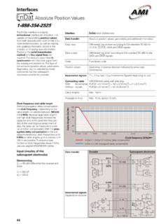
Transcription of Gaging Basics - AMI
1 - Gaging Basics Offered by Automation and Metrology Inc. Please call us if you need any additional help 440 354 6436 Office 440 639 9983 FAX Automation and Metrology, Inc. Liberty St., Painesville OH 44077 Phone 440-354-6436 Fax 639-9983 Page No. * Gage Definition .. 2 * Thread Plug, Gageg .. 2-3 .. * Thread Ring .. 4 * Thread Setting Plug .. 5 * Cylindrical Plug Gages Reversible-Taperlock-Trilock .. 6-7 * Pipe Plug Gages .. 8 * Pipe Ring Gages .. 9-10 * Gage Recalibration .. 11 ENGINEERING DATA *See side tabs for Engineering Data* * Standard System of .. 12-14 1 * Thread Plug Gage Pitch Diameters .. 15-17 * Thread Ring and Setting Thread Plug Gage Pitch Diameters .. , .. 18-20 * Cylindrical Plug Gages Dimensions Reversible-Taperlock-Trilock .. , 20-22 * Gaging Taper Pipe Threads .. 23-25 * NPT and NPTF - Ll Taper Pipe Thread Plug Gages - Dimensions.
2 26 * NPTF - L3 Taper Pipe Thread Plug Gages Dimensions .. 26 * NPT and NPTF - L1 Taper Pipe "Thin" Thread Ring Gages - Dimensions .. 27 * NPTF - L2 Taper Pipe "Thick" Thread Ring Gaoes - Dimensions .. 27 WHAT IS A GAGE? Gages are a means of measurement between two (2) sDecified limits which acceDts or reiects Darts beina oaaed.. , -- - ihe most commonly used are: THF THF 7, ,- 7 EAD PLUG CYLINDRICAL PLUG 7 EAD RING PIPE PLUG 3 EAD SETTING PLUG PIPE RlNG THREAD PLUG GAGES Thread plug gages are used to check an internal threaded hole. The most common thread plug classifica- tions are: - 26 .. a general purpose class of fit. - 3B .. used to check parts with "closer" tolerance requirements. (See pages 15-17 for tolerance) ZZ49LE END THREAD PLUG GAGE TAPERLOCK DESIGN LXXBLE END THREAD PLUG GAGE REVERSIBLE DESIGN '.
3 'orking thread plugs are to be used in an internally ?-eded hole and are not to be used to check a ring gage. - -E zzrt being checked is generally acceptable when the work plug does not enter more than 1% to 3 turns -cent upon customer specifications and the Go work :-OSI enters the threaded hole its entire length. : 7-r 5' = LO VO 00 - Hi Thread R",g Gaga% GO - H,; NO GO = LO 2 There are three (3) styles of working plug gages .. Taperlock. Reversible and Trilock. The taperlock style consists of a Go andlor No Go member(s). The Go member is longer than the No Goand has a chip groove (in larger sizes) which not only adds to ease of identification but also assists in clearing obstructions. The reversible thread plug gage also consists of a Go and No Go Both members are straight and afford the gage user double the life by simply reversing the gage member@), turning the worn portion into the handle.
4 The trilock design is best suited for large size thread plug gages (lY2 inihes and up). ~onsistin~of a Go andlor No Go memberk). the trilock has a bolt fastenina svstem to suppo!i the size and weight. A chip groove is provided on the Go member for ease of identification and clearing obstructions. Proper selection of the drill and tap is required to in- sure that the tapped hole will meet tolerance limits. The Go member not entering the hole may be indicative of in- correct tooling, improper set-up andlor burrs. If the No Go member enters the threaded hole of the part more than three (3) turns it is possible the wrong size threading tool is being used or you have a "bell mouth" hole condition. Gages are normally manufactured and inventoried to class "X" tolerances which refers to pitch diameter, ma- jor diameter, lead tolerances and thread angle tolerances.
5 Class "W tolerances which are recommended for closer product tolerances or final inspection are also available upon request. Both classifications, "X" and "W, are gage manufacturers' tolerances and not the limits. See pages 15-17 tolerances. ,"reed PlW Gem: GO - LO NO GO = HI ,"mad Ring Gayer: 00 . HI; NO GO = LO 3 EXAMPLE: 1/4-20 UNC 28 plug gage .. the "X gage makers' tolerance on the pitch diameter would be .0003 and the "W tolerance would be ,3001. The tolerance is ap- plied (+)plus on the Go gage and (-) minus on the No Go gage. THREAD RING GAGES Thread ring gages are used to check an external threaded part. The most common classes of fit are: - 2A .. a general purpose class of fit and - 3A .. used to check parts with "closer" tolerance requirements. (See pages 18-20 for tolerances.) Other classes of fit and special pitch diameters are available upon request.
6 THREAD RING GAGE 1 ?e pan oelng checked is generally acceplable when - ZFPS not enter the No Go ring gage more than 1% to I -_-3s dependent upon customer specifications. No Go - -= . cages - have an annular groove around the outside for ---.., .. cation. --s Go thr gage checks all functional ;+:-e!iies of tl,, L,,,r,u,d part with the exception of the -- -.. diameter. The products' thread should freely enter --; 3: !'mad ring gage for the entire length of the ---52:d portion. z7 . +r ~ CT3 - HI NO GO-LD mm6P(Yg Gag81 00 - 10, NO GO = H! 4 THREAD SETTING PLUG GAGES Thread sening plugs are to be used to set ring gages only. Their purpose issetting or resetting the ring gages and determining if the ring is within tolerance. Setting plugs are not to be used to check the work piece. To insure the ring gage is still within its tolerance after being put into use, the setting plug gage, both Go and No Go, should be used to verify accuracy.)
7 This also provides the gage user the capability to reset the ring gage as re- quired. Generally, the setting plug is ordered at the same time as the thread ring gage and there could be a cost savinqs when ordering them tooether. Remember, the set plug gage is neededln the manufacturing and certifica- tion of the ring gage and they are matched to each other. THREAD SETING PLUG GAGE THREAD RING GAGE In setting an adjustable thread ring gage, the sealing compound must be removed and the locking screw loosen- ed. Turning the adjusting screw to the right enlarges the ring so that it turns freely onto the thread setting plug. Alter- nately adjusting the adjusting screw and tightening the locking screw, until a firm fit on the threads is achieved, is the proper method of assuring accurate adjustment. A truncated setting plug of standard design will have Thraad R!
8 G Gages: GO = H,; NO 00 - LO mmad Plug Gags=- GO = LO; NO GO - HI 5 1 the crest of the thread truncated for half the length of the gage, unless otherwise specified, giving a full-form por- tion and a truncated portion. In setting thread ring gages to size. the truncated portion controls the Ditch diameter and the full-form portion assures that the proper clearance is provided at the major diameter of the ring gage. The use of the full-form portion along with the truncated por- tion checks the flank angle of the thread gage. CYLINDRICAL PLUG GAGES Cylindrical plug gages, sometimes referred to as pin gages or plain plug gages, are used to check a drilled hole or the minor diameter of a threaded hole. There are three (3) basic styles of cylindrical plug gages: REVERSIBLE (PIN) TAPERLOCK Size Range: 015 lo ,760 Size Range.
9 240 to ,- Size Range. 760 to The attraction of the reversible is that it affords the end- user the oooortunitv to double the wear-life of the aaae by simply thing thegage around and using the otheyeril, resulting in lower gage cost. The reversible cylindrical (pin) gage is designed for size ranges of ,015 to ..760. The taperlock design is held in the handle by means of a tapered shank which provides added holding strength necessary for intermediate size ranges of ,240 to mreed Rug Cfapo. GO - HI; NO GO = 10 mmd Pjug Gagen GO = LO: M GO = Hl 6 The trilock design may be used like a reversible by sim- ply turning the members around. A bolt fastening system is used because of size and weight. The trilock is designed for size ranges ,760 to Double end gages are supplied with (+) plus tolerance on the Go member and (-) minus tolerance on the No Go member.
10 Cylindrical plug gages may be furnished in four (4) tolerance classes, as follows: Class "XX -Very close tolerance and typically used for master gages. Class "X - Close tolerance for products requiring the highest grade of precision. (Most commonly used) Class "Y" - Larger tolerance than class "Xu and used as working gages. Class "Z -Used as working gages for more liberal product tolerances. When selecting gage tolerance it is a good practice to not exceed 10% of the product tolerance. Following are examples of tolerance comparisons for cylindrical plug gages: See page 20 through 22 for dimensions and tolerance. RANGE ABOVE-THRU INCH-METRIC ,015" - .075" .38mm - ,075" - .180" - mmb Rrcg Gagas: GO - H,; NO OD D LO ThrsabPfog Gag*: OO = LO. NO M M H! 7 TOLERANCES-INCHES-MILLIMETRES CLASS XX .00002 ,000508 ,00002.