Transcription of Universal Concentricity Gage - AMI
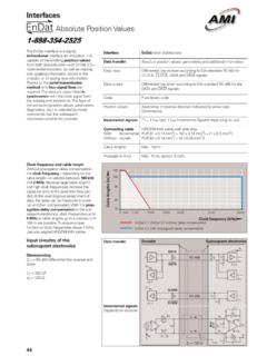
1 Universal Concentricity GageModel H and HL SeriesModel H-10 OPERATING AND MAINTENANCE MANUALD-SA-04 Rev. A2 Our Product Universal Punch Corp. s patented Concentricity gage System is an accurate and reliable instrumentto measure critical features on cylindrical parts. It offers less than 2 microns (.000080 ) accuracy thathas proven results in a variety of industrial applications. Continuous improvement to the modulardesign adapts to meet customer requirements and provide the flexibility necessary for Gaging System The gage System consists of five major features (See Figure 1)1) Adjustable Yoke Assembly with Clamp Arm (A)2) Outboard Roller Support (B)3) Indicator Carriers with Fine Adjustment (C)4) Adjustable (Z-Axis) / Tilting Carriers (D)5) Manual or Motorized Drive System with Timing Belts (E)Note:All Figures used are for illustration purposes only and may not represent exactconfiguration. As features are discussed in this Manual, the orientation of the gage is 1.
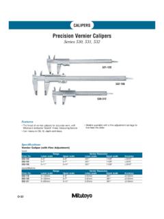
2 gage Assembly Orientation(Model H-20 shown with optional Front Checking Attachment) gage Operation Note: The following operation sequence is provided as a basis for loading, inspectingand unloading a part using a standard gage Assembly. Special features andattachments that may be installed on a particular gage are not addressed. SeeFigure 1 for part Prior to usage of the gage , check Main Rollers and Outboard Rollers for any dirt orcontamination. If necessary, clean with alcohol and a soft Install Dial or Test Indicator(s) into proper carrier (s) (D) and tighten in place using theSwivel Clamp Assembly Thumb Screw or Rear carrier Socket Head Cap Slide and/or tilt carrier (s) (D) out of the way to provide clearance to install Loosen Clamp Knob on Yoke Assembly (A) and raise to a position that allows easyinstallation of Place part on Main Rollers and lower Yoke Assembly (A) into a position that causesthe Top Roller on the Clamp Arm to contact the part Continue to lower the Yoke Assembly (A) so that the spring under the Clamp Armbegins to compress.
3 Clamp Arm should rest at approximately a fifteen (15) degreeangle for proper pressure on Tighten Clamp Knob on Yoke Assembly (A) to secure in Slide Outboard Roller Support (B) into position under Adjust Rollers to contact part in desired area. Tighten Clamp Knob to secure in : Be sure that the part remains horizontal and rests evenly on Main Rollers andOutboard Rollers. Any uneven condition will result in incorrect Tilt carrier (s) (D) to vertical Slide carrier (s) (D) along Shafts (Z-axis) into position required to obtain Loosen Swivel Clamp Assembly Thumb Screw or Rear carrier Socket Head CapScrew on Indicator(s) to allow them to be adjusted to the proper After Indicator is close to measurement area, secure in place by tightening SwivelClamp Assembly Thumb Screw or Rear carrier Socket Head Cap Zero Indicator by using Fine Adjust Knob (C). Ensure that Dial is set at 0 . Using the Drive System (E), rotate part slowly and note movements of the Move indicator to new position (if required) and repeat Step and Slide carrier (s) (D) along Shafts and tilt out of position to allow accessibility of Depress Clamp Arm on Yoke Assembly (A) to raise Top Roller off Remove part from Main Rollers.
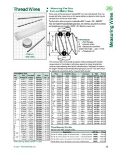
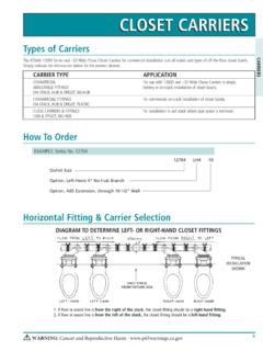
4 Repeat Steps thru for another Yoke Assembly (See Figures 2 and 3)Adjustable, multi-position Arm Yoke Assembly offers a variety of clamping pressures and positions toaccommodate different part diameters. When the proper position is obtained, the Adjusting Knob istightened to hold it securely in 2. Yoke in raisedFigure 3. Yoke in Drive System (See Figures 4 and 5)All Gages come standard with a Manual Drive System consisting of a Drive Knob, two (2) DrivePulleys and two (2) Timing Belts. This design provides a smooth and constant part rotation whileinspecting. UPC also provides an optional Motorized Drive System (fixed or variable speed) availablein 110/120 or 220/230 4. Manual Drive SystemFigure 5. Motorized Drive System(Fixed Speed shown) Carriers (See Figures 6 and 7)All Standard Indicator Carriers assure accurate Indicator Probe positioning and zeroing and providesmooth Indicator movement to increase measuring performance and accuracy.
5 Carriers offer avariety of positions along the Z-axis of the gage to accommodate various lengths. They can be usedwith horizontal test indicators for checking surfaces (runout), parallel test indicators to check faces(runout or perpendicularity) or with standard dial 6. Right Side carrier AssemblyFigure 7. Front Checking Vertical Carriers (See Figures 8 and 9)All Model H and HL Concentricity gage Models come standard with a Rear Vertical carrier . TheseCarriers also offer various positions along the Z-axis, tilt-away for loading and unloading of parts andthe option to use a Dial Indicator instead of a Test Indicator. The can be supplied in a variety ofconfigurations. Figure 8 shows a standard Rear Vertical carrier Assembly with a Dial Indicator Holdersub-assembly. The carrier can also be provided with a Roller Checking Attachment (See Figure 9).Figure 8. Rear Vertical carrier withFigure 9. Roller Checking AttachmentDial Indicator carrier Fine Adjustment (See Figures 10 and 11)Assemblies can be provided with a Fine Adjust Attachment.
6 Figure 10 shows a Dial Indicator Holderwith Fine Adjust and Figure 11 shows a Roller Checking Attachment with Fine Adjust. All of theoptions mentioned utilize the same basic 10. Dial Indicator HolderFigure 11. Roller Checking AttachmentWith Fine Adjustwith Fine Roller Support (See Figure 12)The Model H and HL Gages use an Outboard Roller Support Assembly to cradle the part at theopposite end of the Main Rollers. The Roller Support is adjustable along the Z-axis for various partlengths and can also be adjusted vertically to accommodate different part diameters. The part restson two precision Rollers or carbide balls (optional) and is locked in position by tightening the 12. Outboard Roller Support Stop Set-up (See Figures 13 and 14)The Back Stop Assembly is another option available to ensure that the part does not travel in a lineardirection. It maintains part stability, ensuring proper readings. The Back Stop Assembly is installed inthe rear of the Main Block and can be adjusted to various positions to accommodate various lengthsand diameters using the two Thumb Screw 13.
7 Back Stop AssemblyFigure 14. Back Stop Assembly(Front view)(Rear view) / Calibration ScheduleThe recalibration of the gage Assembly is to be done by authorized personnel only. The gage can bereturned to UPC for a complete calibration, cleaning and certification. The schedule for calibration isas follows: Every 180 days (6 months)The calibration schedule recommended by UPC is based on the following criteria:1. Parts that are being inspected on the gage are a form of steel gage usage, either on the shop floor or in an inspection area, is a maximum of six hours : If other types of abrasive or carbide materials are being used and, the usagetime exceeds six hours, then the scheduled interval will be half of the time durationindicated InspectionsThe following items shall be visually inspected for cracks, wear, scratches, rust and proper fitaccording to the schedule identified:WeeklyMonthlyYearlyMain Rollers XTop Rollers XDrive Belts XCarrier Shafts XSprings XBearing and Liners XKnobs XNylon Washers XRubber Mounting Feet XContact Universal Punch Corp.
8 To obtain an Illustrated Parts Breakdown Drawing for a particular GageModel. Some replacement parts may be ordered by utilizing the drawing and referencing theappropriate Part Number(s). Roller Replacement (See Figure 15)Note: This procedure shall only be performed on standard gage Models (Black). Main Rollerreplacement on precision Models (Gold) shall only be performed by Universal Punch Main Rollers on the Concentricity gage may be replaced if they are worn, scratched or havebeen in use for a long period of time. Figure 18 shows a typical Main Block / Main Roller following steps shall be followed to remove and replace any Main Slowly rotate Drive Knob (C) and slide Belts (F) off of Drive Pulleys (D). Using Hex Key, loosen Set Screw (E) on Drive Pulley (D). Slide Drive Pulley (D) off shaft of Main Roller (B). Remove Nylon Washer (G) from shaft of Main Roller (B). Remove Main Roller (B) from Main Block (A). Remove Nylon Washer (G) from shaft of Main Roller (B).
9 Note: Shaft of Main Roller shall be thoroughly cleaned prior to Lightly coat shaft of Main Roller (B) with Lubricant (Isoflex NBU-15 Mfr.: KluberLubrication).Note: Replace any worn Nylon Washers (G). Place Nylon Washer (G) onto shaft of Main Roller (B). Slide Main Roller (B) into Main Block (A) from Place Nylon Washer (G) onto shaft of Main Roller (B). Install Drive Pulley (D) onto shaft of Main Roller (B). Using Hex Key, tighten Set Screw (E) on Drive Pulley (D). Repeat Steps 2 through 12 for second Main Slowly rotate Drive Knob (C) and slide Belts (F) onto Drive Pulleys (D)Note: After replacing Main Rollers, it is recommended that the assembly be calibrated in accordancewith Section of this manual. Runout of Main Rollers as specified in Section must 15. Main Roller / Main Block establish a standard procedure for the calibration of all Concentricity All Concentricity Gages used to measure, test, inspect, or otherwise examine items todetermine compliance with set This procedure also applies to Gages returned to Universal Punch Corp.
10 For Calibration A procedure performed under specific conditions that establishes therelationship between values measured and known values derived from Recalibration A systematic check and adjustment of the accuracy and precision of aparticular item performed at prescribed Verification A check for proper zero and limited confirmation of an items accuracyby comparing it to a known Runout (Measured in Full Indicator Movement or FIM ) The measurement of surfacevariation that occurs relative to an axis of rotation. It is the total amount of movement(FIM) on an indicator after on full revolution of a part that is rotated about its datumaxis. It may be measured parallel (outer surface) or perpendicular (face) to the Materials and Conditions Granite Surface Plate with floor vibration Calibrated gage Test Pin traceable to (size depends on gage being tested) Electronic gage Head or gage Probe (LVDT) with Amplifier at 10:1 Cleaning solution and Lint-free Temperature controlled environment at 2 with _ change per Special Verify that the calibration status of all equipment being used is Do not use abrasive stones to remove imperfections on the gage Roller Use caution when removing dirt, oil and other foreign substances when Tolerances (Runout).