Transcription of Gas Pressure - Maxitrol
1 2011, Maxitrol Company. All Rights Pressure Regulators CatalogFor Industrial Engines and Generator Sets 2011, Maxitrol Company. All Rights Pressure REGULATORSFor Industrial Engines and Generator SetsService and or installation must be performed by a trained, experienced service technician. No untrained person should attempt to install, maintain, or service a gas Pressure regulator. All products, including gas Pressure regulators, used with combustible gas MUST be installed and used strictly in accordance with instructions of the manufacturer, with government codes and regulations, and plumbing codes and practices. Maxitrol s gas appliance Pressure regulators should be installed and operated in accordance with our Safety Warning Bulletins . Maxitrol Company is NOT responsible for any errors or omissions in reliance by anyone of any information set forth in this catalog without additional reference to local requirements and applicable ordinances or worldwide approvals and certifications available upon inquiry.
2 2011, Maxitrol Company. All Rights Table of Contents RV Series - Straight-Thru-Flow Design Description .. 4 Specifications .. 4 Certifications .. 5 Pressure Tap Identification Numbers .. 6 Capacities .. 6 Spring Selection Charts .. 7 Dimensions .. 8 Cutaway w/Callouts .. 9 Pressure Drop Chart .. 22 R/RS Series - Balanced Valve Design Description .. 10 Specifications .. 10 Certifications .. 11 Pressure Tap Identification Numbers .. 12 Capacities .. 12 Spring Selection Charts.
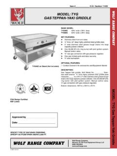
3 13 Dimensions .. 14 Cutaway w/Callouts .. 15 Pressure Drop Chart .. 23 210 Series - Balanced Valve Design Description .. 16 Specifications .. 16 Certifications .. 17 Pressure Tap Identification Numbers .. 18 Capacities .. 18 Spring Selection Charts .. 19 Dimensions .. 20 Cutaway w/Callouts .. 21 Pressure Drop Chart .. 24 2011, Maxitrol Company. All Rights (M), RV53(M) STRAIGHT-THRU-FLOW REGULATOR DescriptionMaxitrol s original straight-thru-flow (STF) design regulators are non-lockup type regulators for high capacities at low inlet pressures.
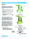
4 The difference between STF design and other type regulators is the conical valve. The cone principal permits gas to flow straight through the regulator without changing directions. Frictional flow resistance is reduced, resulting in greater capacity. An improved flow pattern provides accurate, sensitive regulation at extremely low Pressure differentials. Typical applications include residential, commercial, and industrial gas-fired appliances and equipment used on low/medium Pressure gas SERIESS traight-Thru-Flow Design SpecificationsVibration ResistantAdjusting Screw(inside)Welch Plug/ Seal CapPressure TapsPipe Sizes .. 1/2 to 3 threaded connections with NPT threads or ISO7-Rp threads. 4 Flange only. RV52(M): 1/2 x 1/2 , 3/4 x 3/4 RV53(M): 3/4 x 3/4 , 1 x 1 RV61(M): 1 x 1 , 1 1/4 x 1 1/4 RV81(M): 1 1/4 x 1 1/4 , 1 1/2 x 1 1/2 RV91(M): 2 x 2 , 2 1/2 x 2 1/2 RV111(M): 2 1/2 x 2 1/2 , 3 x 3 RV131(M): 4 x 4 Housing Material.
5 Aluminum or cast iron (RV131 only).Mounting .. RV52(M), RV53(M), RV61(M) multi-positional mounting (if ball check vent limiting device is installed, mount in an upright position only). RV81(M), RV91(M) (12A04 or 12A34), RV111(M), RV131, upright position only. Install with gas flowing as indicated by the arrow on bottom casting. NOTE: All Maxitrol gas Pressure regulators should be installed and operated in accordance with Maxitrol s Safety Warning : Models with ISO7-Rp threads are designated by the suffix M ( RV52M). 2011, Maxitrol Company. All Rights Pressure Regulators for Industrial Engines & Generator SetsULCSACES tandard/Directive:ANSI/UL 842 ANSI 88 and GAD 2009/142/EECGas Types:Suitable for natural, manufactured, mixed gases, liquefied petroleum gases, and LP gas-air for natural, manufactured, mixed gases, liquefied petroleum gases, and LP gas-air Families 1, 2, and 3 according to EN437 Maximum Inlet Pressure :RV52(M), RV53(M), RV61(M), RV81*, RV91*, RV111*, RV131*:1/2 psi ( kPa)RV52, RV53, RV61, RV81, RV91, RV111: 1/2 psi ( kPa)RV52M: psi (10 kPa)RV53M,RV61M,RV81M, RV91M,RV111M: psi (20 kPa)Outlet Pressure :RV52(M), RV53(M), RV81*, RV91*, RV111*, RV131*:3 to 12 ( to kPa)RV61(M):1 to 6 ( to kPa)RV52, RV53, RV81, RV91, RV111:3 to 12 ( to kPa)RV61:2 to 12 ( to kPa)RV52M: 1 to 22 ( to kPa) RV53M, RV61M: 1 to 30 ( to kPa)RV81M, RV91M, RV111M.
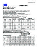
6 1 to 42 ( kPa to kPa) Ambient Temperature Ranges:---RV52, RV53, RV61, RV81, RV91, RV111:-40 to 205 F (-40 to 96 C) All Models:5 to 176 F (-15 to 80 C)Vibration Resistant Adjusting Screw:RV81(M): R8111-001 RV91(M): R9111-001 NOTE: Models with ISO7-Rp threads are designated by the suffix M ( RV52M).*RV81, RV91, RV111, RV131 are UL pending. Certifications 2011, Maxitrol Company. All Rights SERIESS traight-Thru-Flow DesignModelPressure Drop** - inches water column (kPa) ( ) ( ) ( ) ( ) ( ) ( ) ( ) ( ) ( ) ( )RV52(M)151 ( )214 ( )262 ( )302 ( )338 ( )370 ( )400 ( )427 ( )453 ( )478 ( )RV53(M)217 ( )306 ( )375( )433( )484( )530 (15)573( )612 ( )650( )684( )RV61(M)379 ( )536 ( )675 ( )759 ( )848 (24)929 ( )1004 ( )1073 ( )1138 ( )1200 ( )RV81(M)780 ( )1102 ( )1350 ( )1559 ( )1743 ( )1909 (54)2062 ( )2204 ( )2339 ( )2465 ( )RV91(M)1212 ( )1714 ( )2100 ( )2424 ( )2711 ( )2969 ( )3208 ( )3429 ( )3637 (103)3834 (108)RV111(M)2742 (78)3878 (110)4750 (134)5485 (155)6132 (175)6718(190)7256 (205)7757 (219)8227(233)8572 (243)RV131(M)4734(134)6695(190)8200(232) 9468(268)10586(300)11596(328)12525(354)1 3390(380)14202(402)14971(424)NOTE: Models with ISO7-Rp threads are designated by the suffix M ( RV52M).
7 **See page 22 for Pressure drop chart. Pressure Tap Identification Numbers Capacities: Expressed in CFH (m3/h) @ sp gr gasModelInletOutletFlow - UL MaxFlow - CSA MaxRV52(M)21450 CFH450 CFHRV53(M)690 CFH690 CFHRV61(M)12900 CFH900 CFHRV81(M)*---2500 CFHRV91(M)*---3275 CFHRV111(M)*---------7500 CFHRV131------NOTE: Models with ISO7-Rp threads are designated by the suffix M ( RV52M).*NOTE: RV81, RV91, RV111, RV131 are UL pending. 2011, Maxitrol Company. All Rights Pressure Regulators for Industrial Engines & Generator SetsUL Certified SpringsModelExpressed in inches water column (kPa)RV52(M)---3 to 6 ( to )4 to 8 (1 to 2)5 to 12 ( to 3)RV53(M)---3 to 6 ( to )4 to 8 (1 to 2)5 to 12 ( to 3)RV61(M)2 to 5 ( to )3 to 6 ( to )4 to 8 (1 to 2)5 to 12 ( to 3)RV81, RV91, RV111, RV131 are UL Pending Spring Selection ChartsCE Certified SpringsModelExpressed in inches water column (kPa)RV52M1 to ( to )2 to 5( to )3 to 8( to 2)4 to 12(1 to 3)10 to 22( to )------RV53M1 to ( to )2 to 5( to )3 to 8( to 2)4 to 12(1 to 3)10 to 22( to )15 to 30( to )---RV61M1 to ( to )2 to 5( to )3 to 8( to 2)5 to 12( to 3)10 to 22( to )15 to 30( to )---RV81M1 to ( to )2 to 5( to )3 to 8( to 2)4 to 12(1 to 3)10 to 22( to )15 to 30( to )20 to 42(5 to )RV91M1 to ( to )2 to 5( to )3 to 8( to 2)
8 4 to 12(1 to 3)10 to 22( to )15 to 30( to )20 to 42(5 to )RV111M1 to ( to )2 to 5( to )3 to 8( to 2)4 to 12(1 to 3)10 to 22( to )15 to 30( to )20 to 42(5 to )RV131M2 to ( to )---3 to 8( to 2)4 to 12(1 to 3)10 to 22( to )15 to 30( to )20 to 42(5 to )NOTE: Models with ISO7-Rp threads are designated by the suffix M ( RV52M).CSA Certified SpringsModelExpressed in inches water column (kPa)RV52---3 to 6 ( to )4 to 8 (1 to 2)5 to 12 ( to 3)RV53---3 to 6 ( to )4 to 8 (1 to 2)5 to 12 ( to 3)RV612 to 5 ( to )3 to 6 ( to )4 to 8 (1 to 2)5 to 12 ( to 3)RV81---3 to 6 ( to )4 to 8 (1 to 2)5 to 12 ( to 3)RV91---3 to 6 ( to )4 to 8 (1 to 2)5 to 12 ( to 3)RV111---3 to 6 ( to )4 to 8 (1 to 2)5 to 12 ( to 3) 2011, Maxitrol Company. All Rights SERIESS traight-Thru-Flow Design Dimensions: Expressed in inches (millimeters)ModelVentSwing RadiusDimensionsABCDRV52(M)1/8 (91) (124) (32) (81) (83)RV53(M)1/8 (99) (132) (33) (95) (99)RV61(M)1/8 (122) (164) (41) (111) (138)RV81(M)3/8 (162) (213)2(51)6(153)7(178)RV91(M) Pipe1/2 (216) (275) (60) (165) (232)M: 1/2 ISO7RV91(M) Pipe1/4 (212) (267) (62) (181) (232)RV111(M)3/4 (284) (373) (89)9(229) (324)M: 3/4 ISO7RV131(M)3/4 (462) (592) (130) (353)18(457)M: 3/4 ISO7 NOTE: Models with ISO7-Rp threads are designated by the suffix M ( RV52M).
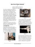
9 NOTE: Dimensions are to be used only as an aid in designing clearance for the valve. Actual production dimensions may vary somewhat from those (M), RV81(M), RV91(M)RV111(M), RV131(M)RV52(M), RV53(M) 2011, Maxitrol Company. All Rights Straight-Thru-Flow Design 1 Welch Plug/Seal Cap 2 Vibration Resistant Adjusting Screw 3 Top Housing 4 Diaphragm 5 Stem 6 Bottom Housing 7 Seal Cap Gasket 8 Stack 9 Spring10 Vent Limiting Device11 Diaphragm Plates12 Valve13 Bottom Plate Gasket14 Bottom Plate12391011467851213 Gas Pressure Regulators for Industrial Engines & Generator Sets14 2011, Maxitrol Company. All Rights (S)(Z)(M), R500(S)(Z)(M), R600(S)(Z)(M) BALANCED VALVE REGULATORR/RS SERIESB alanced Valve Design Specifications Description he R & RS regulators are ideal for industrial applications, capable of controlling Pressure at extremely low flows.
10 The double diaphragm balanced valve design makes it possible to build a regulator that is physically small yet has good capacity characteristics. They are able to maintain steady outlet Pressure control with widely varying inlet pressures. Zero governor models Sizes .. 3/8 to 1 threaded connections with NPT threads or ISO7-Rp threads. R400(S)(Z)(M): 3/8 x 3/8 , 1/2 x 1/2 R500(S)(Z)(M): 1/2 x 1/2 , 3/4 x 3/4 R600(S)(Z)(M): 3/4 x 3/4 , 1 x 1 Housing Material .. 1/8 NPTM ounting .. R400(S)Z(M) mount in an upright position only. R400(S)(M), R500(S)(Z)(M), R600(S)(Z)(M) suitable for multi- positional mounting. If ball check vent limiting device is installed, mount in an upright position only. Install with gas flowing as indicated by the arrow on bottom casting. NOTE: All Maxitrol gas Pressure regulators should be installed and operated in accordance with Maxitrol s Safety Warning : Models with ISO7-Rp threads are designated by the suffix M ( R400SM).