Transcription of Gate-drive Recommendations for Phase Control …
1 Application note Gate-drive Recommendations for Phase Control and Bi-directionally Controlled Thyristors IGMIGon100 %90 %10 %IGM AIGon IGTdiG/dt 2 A/ str 1 stp(IGM) sdiG/dttrtp (IGM)IG (t)ttp (IGon) 2 Doc. No. 5 SYA2034-02 June 07 Gate-drive Recommendations for Phase Control and Bi-directionally Controlled Thyristors Application Note Bj rn Backlund, Thomas Setz J rg Waldmeyer, Eric Carroll ABB Switzerland Ltd Semiconductors June 2007 Table of Contents: 1 2 Gate-drive Recommendations AND APPLICATION GATE DESIGN AND CHARACTERISTICS OF ABB Recommendations WITH REGARDS TO GATE-CURRENT, Gate-drive AND Recommendations FOR CROW-BAR AND OTHER HIGH DI/DT RC-SNUBBER AND PARASITIC CAPACITANCE BACK-PORCH CURRENTS AND PICKET-FENCE GATE CURRENT DURING REVERSE GATE CURRENT TRIGGERING CONSIDERATIONS FOR THE SERIAL AND PARALLEL CONNECTION OF SPURIOUS TRIGGERING DUE TO ELECTRO-MAGNETIC 3 ADDITIONAL TRIGGER SIGNAL TRANSMISSION AND POWER SUPPLY FOR THE Gate-drive APPLICATION 3 Doc.
2 No. 5 SYA2034-02 June 07 1 IntroductionThe main purpose of a gate-driver for a Phase Control thyristor (PCT) or a Bi-directionally Controlled Thyristor (BCT) is to provide a gate current of the right amplitude, at the right time and of the right duration. This would seem simple but the analysis of failed thyristors due to inadequate gate pulses leads to the conclusion that the proper design of a Gate-drive unit is not trivial. This application note points out some of the most important Gate-drive design rules. A thyristor is a current-controlled bipolar semiconductor, unlike MOSFETs or IGBTs which are voltage controlled. Therefore, a thyristor Gate-drive unit is primarily a current source, supplying a specifically shaped current pulse from gate to cathode. The voltage drop along the gate-to-cathode path is a function of the gate current, the anode current and the internal impedance between gate and cathode.
3 For this reason, thyristor manufacturers specify gate-current pulses rather than gate-voltage pulses. 2 Gate-drive Recommendations and application aspects Definitions To explain the definitions of triggering-data for ABB thyristors we use, as an example, the tabular triggering-data from the data sheet of the 5 STB 18U6500 BCT with definitions according to international standard IEC 60747. Triggering Maximum rated values 1) Parameter Symbol Conditions min typ max Unit Peak forward gate voltage VFGM 12 V Max. rated peak forward gate current IFGM 10 A Peak reverse gate voltage VRGM 10 V Gate power loss PG see Fig. 1 W Characteristic values Parameter Symbol Conditions min typ max Unit Gate trigger voltage VGT Tvj = 25 C V Gate trigger current IGT Tvj = 25 C 400 mA Gate non-trigger voltage VGD VD = x VRM, Tvj = 125 C V Gate non-trigger current IGD VD = x VRM, Tvj = 125 C 10 mA 1) Maximum Ratings are those values beyond which damage to the device may occur.
4 Table 1 Tabular trigger data for device 5 STB 18U6500. VFGM: Maximum allowable forward gate-voltage. This voltage may instantaneously occur across the gate and cathode terminals if a strong initial gate pulse with a short rise-time and a high amplitude is applied and the anode current rises with a high di/dt. IFGM: This value indicates the maximum allowable gate-current, primarily determined by the gate contact. It is a maximum rating, valid for short pulses 100 s. For DC operation, IFGM must be reduced further in order not to exceed the maximum continuous gate power-loss, PG. Applying an IFGM above the limiting value may be destructive due to over-stress of the internal gate-contact interfaces even if the average gate-power is within the specified limits. VRGM: Maximum reverse gate-voltage.
5 Exceeding this rating will cause excessive reverse gate power-loss. PG: Gate power-loss. This is the maximum gate-power the thyristor can withstand without being damaged in the gate region. Values for typical conditions are presented in Fig. 1. 4 Doc. No. 5 SYA2034-02 June 07 VGT, IGT: Gate trigger-voltage and current, respectively, defined as the minimum gate-voltage/current necessary to trigger the thyristor. These parameters are measured with an anode voltage of 6 V at a junction temperature of 25 C. VGT and IGT decrease with increasing anode voltage and temperature. Note that these values are measured at quasi-stationary conditions. These values will just trigger the device and may lead to its destruction under worst-case conditions. Substantially higher values are needed in practice for operation under dynamic conditions, as will be explained later.
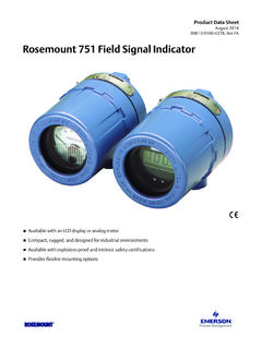
6 VGD, IGD: Gate non-trigger voltage and current, respectively, defined as the maximum admissible gate voltage/current which will not provoke triggering of the thyristor. These ratings are defined at quasi worst-case conditions of VD = VDRM and Tvjmax and will have higher values at reduced anode voltage and junction temperature. VGD and IGD are of particular importance in a noisy environment where electromagnetic interference can lead to spurious thyristor triggering. This may not only cause a malfunction of the converter but is also dangerous for the thyristor because marginal (localised) firing may destroy the gate structure. Special measures such as gate-signal filtering, should be implemented in these cases. In addition to the tabular data, the data sheet also includes a gate characteristic curve, see Fig.
7 1. Fig. 1 Gate characteristic curve from the 5 STB 18U6500 data sheet This curve shows the spread of VFG as a function of IFG considering both the effects of temperature, within the whole operational temperature range and whether the voltage is measured under static or dynamic conditions. The lower limit is the minimum expected DC gate voltage at Tj = -40 C and the upper limit the highest expected dynamic gate-voltage at Tvjmax. The dotted hyperbolic lines show the instantaneous gate-power limits while the vertical dotted line represents the absolute gate-current limit of 10 A which is not to be exceeded irrespective of duty cycle and pulse width. The instantaneous gate-power limits are defined for three different pulse widths, where the pulse width tp is either the width of a single rectangular pulse or the duration of a picket-fence pulse-train defined as time T in Fig.
8 9. For a single rectangular pulse, the load-line, see Fig. 7, must be drawn on the left side of the corresponding hyperbolic line for the appropriate pulse width. For a picket-fence pulse-train it must be assured that the gate current, the resulting gate voltage and the duty cycle, defined as the ratio Tpn/Trep in Fig. 9, are selected to limit the rms-power to a value below the allowable PGM of the chosen tp. Upper limitLower limit 5 Doc. No. 5 SYA2034-02 June 07 Gate design and characteristics of ABB thyristors Small-area devices can be triggered properly by a relatively moderate current applied to a small gate region in the center of the device. For large-area devices of similar gate design, a substantial current would be required and it would also then take a relatively long time to get the whole device conducting.
9 To avoid these problems, ABB uses amplifying gates with interdigitation for large-area devices. The amplifying gate allows even the largest thyristors to be triggered with a low external gate-current. This is achieved by integrated gate-current amplification and allows the user to trigger all ABB PCTs and BCTs with the same gate-unit design. The amplifying gate consists of an auxiliary thyristor integrated in the main thyristor. This auxiliary thyristor is first triggered and supplies the required gate-trigger current for the main thyristor from the supply (anode) voltage. Schematics of the working principle and its implementation into the silicon wafer are shown in Figs 2 and 3. Fig. 2 Basic principle of the amplifying gate Fig. 3 Lateral integration of the amplifying gate To further improve the turn-on behaviour of the device, the auxiliary thyristor structure may be distributed over the whole thyristor area, thus accelerating the spread of the conducting region during turn-on.
10 This reduces turn-on losses and allows higher di/dt ratings as compared to simple central-gate structures. ABB frequently use the T-gate design for the distributed auxiliary thyristor structure shown in Fig. 4. 6 Doc. No. 5 SYA2034-02 June 07 Fig. 4 View of thyristor wafer with distributed gate (T-Gate) The gate characteristics for a device with amplifying gate can be seen in Fig. 5. A repetitive AC gate current with peak value 10 A is applied and in Fig. 5, two kinks can easily be seen representing the triggering of the auxiliary and subsequently, the main thyristor. Fig. 5 Amplifying gate characteristic of thyristor 5 STP 26N6500 Recommendations with regards to gate-current, Gate-drive and load-line Even though a thyristor can be triggered at static conditions by a current level of IGT, a gate current with an amplitude of several times IGT is needed for proper triggering achieving the desired performance at dynamic conditions.