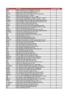
Transcription of Gauges Total Gas Load - Vacuümtechniek
1 System Pressure Total Gas load Materials Selection & Outgassing System Pumping Speed Gauges System Operation Discussion on Accelerator VacuumVacuum SystemsBasic UHV SystemUHVCHAMBERTURBOPUMPSCROLLPUMPION & TSPPUMPION GAUGED egrees Of VacuumULTRAHIGH10-9to 10-12 TORRHIGH10-3to 10-9 TORR>30M to 10-3 TORRV acuum CharacteristicsPressure(Torr)Major Gas (N2,O2,H2O, Ar, CO2) Water Vapor (75 %- 95%)H2O, CO CO, N2, H2CO, H2H2 (3x10⁵molecules/cm3) Vacuum System Performance Vacuum system performance is determined by System Design (volume, conductance, surface, materials) Gas load (rate gas evolves within or enters the volume) Pump Performance (pump speed, compression) Equilibrium Pressure (P)in a vacuum system is determined by the Total Gas load (Q)and the System Pumping Speed (S)SQP=Vacuum System Gas load Vacuum system gas load results from Leaks (real and internal leaks) Surface Condition (outgassing and virtual leaks) System Materials (diffusion and permeation)PermeationOutgassingBackstrea mingInternalLeaksRealLeaksVirtualLeaksDi ffusionThis relation provides approximate pumpdown times in rough vacuum.
2 Outgassing becomes significant at lower pressures and accuracy fails. =liPPSV ctlnSystem Pressure - Rough VacuumThe pressure evolution in a vacuum system of volume Vand effective pumping speed Sis given by:P(t) = Pi exp (-S * t / V)System Pressure - Leaks or PermeabilityIf Q represents a constant gas load due to leaks or permeability of the vessel walls then the ultimate pressure is determined by the gas load and system pumping speed rather than a physical limitation of the =PSQdtdPV =+ Thus a term for the constant gas load is added System Pressure - OutgassingFor qualitative purposes, the outgassing rate of a surface in high vacuum can be represented as: teQQ =0where Q0is the initial outgassing rate, t is the time, and is rate outgassing decays with time (assumed to be constant over a reasonable time). btatBeAeQ +=System Pressure - PumpdownThe solution for pressure decay relative to time that includes the volume gas (1st term), outgassing (2nd term), leaks and permeation (3rd term) is given by:PSQeQdtdPVt =++ 0 Gas load Limiting PumpdownPressure (Torr)10+310-010-310-610-9 TimeVolumeDesorptionDiffusionPermeationV olumeDesorptionDiffusionPermeationPressu re DecayTotal Gas Loadl/sT10T10l/s 1000-9-12 = = QPSPERMEATIONDIFFUSIONOUTGASLEAKVOLUMETO TALQQQQQQ++++=The gas load is the rategas enters the system volumeThe Total gas load on a vacuum system is comprised of: Q (gas load , throughput, leak rate) is expressed in units of pressure volume/time Torr liters/sec, atm cc/sec, sccm, mBar liters/sec, Pa m3/hrExample.
3 To reach 10-12 Torr in a system with 1000 l/s pumping speed, the gas load must be less than 10-9 Torr of Adsorbed GasP(mbar)10-310-610-9 Molecules on SurfaceMolecules in ,000 Time to FormMonolayer (sec) x x 103 AqQoutgasoutgas =Rate of outgassing is dependent upon the base material, temperature, time and treatment. Untreated (as received) Machined (cutting oil used, ) Degreased (method and solvents) Post fabrication treatment (baking, degassing) vacuum. the toexposed area surface theisA andareaunit per outgassing of rate theis whereoutgasqDegassing By BakingTime (Arbitrary Units)Pressure (Torr)10-210-410-610-810-10 HeatingWithout Baking10-12 With Baking110102103 Common UHV Materials Stainless Steel: use as vacuum chambers, outgassing rate, Weldability, Corrosion resistanceCopper: Used as conductors and sealsLow outgassing rate if properly cleanedAluminum: use as chambers due to thermal property and costHigher outgassing, harder to weld Ceramics(Alumina (Al2O3)) : insulators Other metals and inorganic compound.
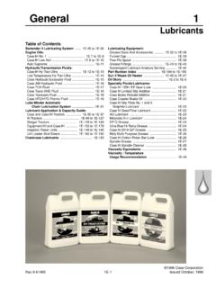
4 Inconel, outgassing rates*1 hour10 hours >24 hrs untreated degreased polished bakedAluminum (anodized)3x10-53x10-78x10-83x10-53x10-5 N/A5x10-10 Aluminum8x10-75x10-81x10-108x10-71x10-81 x10-85x10-13 Brass2x10-66x10-71x10-71x10-61x10-68x10- 6N/ABeryllium1x10-65x10-71x10-91x10-65x1 0-71x10-6N/ACopper1x10-75x10-91x10-101x1 0-71x10-81x10-91x10-12 Copper (OFHC)8x10-92x10-93x10-118x10-98x10-95x1 0-71x10-12 Delrin6x10-61x10-77x10-76x10-6not availablenot available8x10-7 Lead1x10-72x10-84x10-91x10-85x10-81x10-8 N/AMild Steel2x10-62x10-73x1082x10-65x10-75x10-8 5x10-101018 Steel (Ni plated)2x10-65x10-71x10-8not availablenot availablenot availablenot availableGold Sheet8x10-8not available5x10-9 8x10-81x10-8not availablenot availableTitanium1x10-9not available5x10-101x10-9not availablenot available2x10-12 Stainless steel5x10-81x10-81x10-107x10-81x10-95x10 -93x10-13 Exposure to vacuumSurface ConditionOutgassing rates in Torr liter/sec cm2*Data taken from several sources, averaged for air. For info on specificmaterial or gas specie refer to original outgassing rates (cont'd)1 hour10 hours >24 hrs untreated degreased polished bakedEpoxy (Shell Epon)2x10-51x10-6not availablenot availablenot availableN/A8x10-8 Buna N8x10-62x10-68x10-78x10-68x10-7N/A4x10-8 Neoprene3x10-68x10-74x10-83x10-66x10-7N/ A2x10-9 Mylar8x10-71x10-77x10-98x10-7N/AN/A2x10- 9 Acrylic2x10-61x10-65x10-72x10-68x10-7N/A 1x10⁻⁸ Teflon (poly fluoro lene)2x10-78x10-82x10-82x10-7N/AN/A8x10- 9 Nylon (polyamide)5x10-63x10-74x10-85x10-6N/AN/ A6x10-9 Lexan (polycarbonate)7x10-72x10-76x10-81x10-7N /AN/A8x10-9 PVC5x10-73x10-71x10-75x10-7N/AN/A8x10-8 Silicon rubber7x10-68x10-76x10-87x10-72x10-7N/A6 x10-10 Silastic (sealant)5x10-53x10-66x10-78x10-5N/AN/A5 x10-8 Viton8x10-75x10-82x10-88x10-71x10-7N/A5x 10-10 Steatite (ceramic)5x10-81x10-87x10-9N/AN/AN/AN/AP yrex (7740)
5 1x10-72x10-85x10-9not availablenot availableN/A2x10-9 Exposure to vacuumSurface ConditionOutgassing rates in Torr liter/sec cm2To achieve the best possible vacuum or lowest system pressure with a given pump, it is necessary to maximize effective pumping speed at the chamber while minimizing gas = C >> SSEFF= SC ~ SSEFF= S / 2C<< SSEFF= CMaximum theoretical pumping speed SEFF into a 12 diamchamber is about 8000 liter / secSCS + C1 + S / CSSystem Pumping Speedd = diameter of tube in cml = length of tube in cmT = temperature (K)M = in molecular flow (Long round tube)C = x x TMl(l/sec)d3 Example: 4 cm diameter, 100 cm tube, N2, 295 KC = ~ 8 l/sSeries ConductanceSeries ConductanceCT= 200 x 200200 + 200(l/s)CT= 100(l/s)SYSTEMPUMPC1C2 Tube (C1): 200 l/sBaffle (C2): 200 l/sSeries ConductanceSeries ConductanceTube + Baffle (C1+2): 100 l/sPump (C3):200 l/sCT= 200 x 100 (l/s)200 + 100CT= 67(l/s)SYSTEMPUMPC1+2C3 Turbomolecular PumpROTOR BODYHIGH PUMPING SPEEDHIGH COMPRESSIONEXHAUSTHIGH FREQ.
6 MOTORINLET FLANGESTATOR BLADESBEARINGBEARINGM oleculeVMoving Wall with Speed VTURBOMOLECULAR PUMP (TMP)PRINCIPLE OF OPERATIONCOMPRESSION RATIO FOR VARIOUS GASESAS A FUNCTION OF THE FORELINE PRESSURE10-1102110 FORELINE PRESSURE (MBAR)10-22525252510310510710910 NitrogenHeliumHydrogenION PUMP PRINCIPLE OF OPERATION Electric discharge in crossed electric and magnetic field (Penning cell) Ion bombardment of the cathode Deposition of a chemically reactive film (Ti) (Sputtering) Gas sticks on the Ti film (chemisorption)Ion pump96 Ion PumpsDiode and triode schematicallyIon Pump Pumping SpeedGauge Pressure Ranges10310-810-1110-1010-910-710-610-51 0-410-310-210-1100101102 ThermocouplePiraniIon gaugeCold cathodeCapacitance manometerHot filament (BA)PressureUltra highvacuumHigh vacuumRough vacuumAtmBourdonRGAI onization current is the measure of pressureIon gaugeCross-section1. Use turbo and scroll pumps to rough chamber and sump to Bake at highest allowable temperaturefor several (overnite) Turn on TSP/ion pump towards end of bake Valve out rough pump systemSystem OperationPumpdown Curves